



Trace Repair and Jumper Wires on PCB Assemblies: 7 Rules
A trace repair is the last resort before a board is scrapped. A conductor that has been cut by a probe, torn during rework or cracked by repeated flexing can often be restored, but the repair has to carry the same current, survive the same vibration and appear in the build record, or the unit should not ship. That judgement is engineering rather than workshop preference.
The most common repair is a jumper wire soldered between two accessible points on the same net, with the damaged section isolated from the circuit. It works well on a short, low frequency signal net and badly on an impedance controlled line or a high current path. Knowing which is which before the iron is switched on saves a great deal of wasted effort.
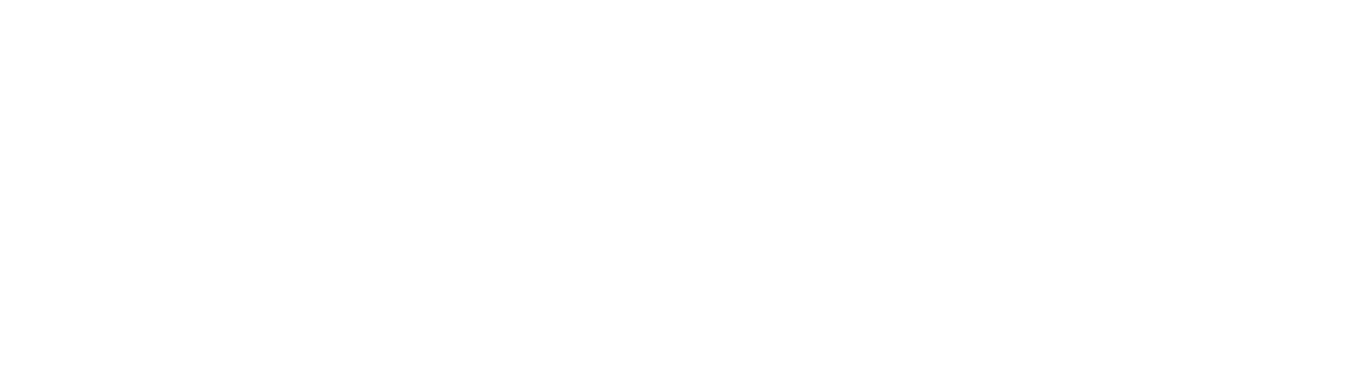
Deciding Whether a Trace Should Be Repaired
The first question is what the net does. A low current logic signal can tolerate the extra inductance of a wire and the small change in resistance that comes with it. A controlled impedance line cannot, because the wire destroys the geometry that set the impedance, and the reflection it creates will show up as a functional failure long after the repair has been signed off.
Current capacity is the second question. A jumper wire has to offer at least the equivalent cross section of the trace it replaces, and a little more if the wire is long, because the resistance of the repair adds to the resistance of the net. Where the trace is part of a plane, or where several conductors in the same area have been damaged, the honest answer is usually scrap. Repair standards put a limit on how many repairs a single board may carry, and that limit exists for a reason.
Preparing the Repair Site
The site has to expose clean copper at both ends of the repair without damaging anything around it. Solder mask can be removed by local abrasion with a fine tool, or by a controlled scrape with a heated blade, but never by dragging a scalpel across neighbouring conductors. The copper underneath should be bright and free of oxide before any attempt is made to solder to it.
Where the pad at one end has also been damaged, the pad repair has to be completed first, because a wire soldered to a loose pad will fail at the pad rather than at the wire. The same preparation logic as any rework site applies here: clean, dry, supported, and inspected under magnification before the joint is made.
Sizing and Routing the Jumper Wire
The wire should be solid, tinned copper with insulation that tolerates the temperature of the soldering operation. Insulated wire is preferred, because a bare wire lying across the mask can short to anything it touches. The gauge follows the current, and the length should be the shortest that reaches both anchor points comfortably.
Routing matters as much as the electrical specification. A jumper that crosses a high speed net couples to it, and a jumper that lies over a pad can be crushed during assembly. The wire should run flat against the board, away from sensitive nets, and should not cross a route that will later be used by a screw, a standoff or a connector housing.
Soldering the Repair
Both ends of the repair should be tinned, and the exposed copper should be preheated before the wire is placed. A large thermal mass, such as a plane connection, needs the same approach as any heavy joint, and the heat should be applied so that the alloy flows onto the trace rather than sitting on top of it. A joint that looks bright but has not wetted the copper will fail later.
The wire should be anchored so that the solder joints do not carry any mechanical load. A small bend, a tack down point or a short length of the wire laid flat and bonded is enough. Where the wire has to leave the board surface, it should do so where it cannot be caught by tooling or by the next handling step.
Bonding the Wire With Epoxy
Epoxy is the mechanical part of the repair. It holds the wire against the board, spreads any load across the laminate and seals the exposed copper against moisture. It is not a conductor, so a repair that depends on epoxy for continuity has not been made properly.
The adhesive should be applied in small dots along the wire and over the exposed copper at both ends, then cured to the supplier schedule. A two part epoxy with a long working time is easier to place accurately than a fast curing grade, and the cured bead should be checked to confirm that it has bonded to both the wire and the laminate rather than sitting on a film of flux.
Thermal Damage and Rework Limits
Every repair is another thermal cycle for the laminate. A pad that has already been reworked twice has less adhesion than one that has been reworked once, and the trace beside it has been heated along with the joint. A repair that takes three attempts is usually a sign that the technique or the tool is wrong rather than that the board is difficult.
Where the same repair fails repeatedly at the same reference, the design should be reviewed, because the site is being asked to survive more handling than the layout allows. That is a design finding rather than an operator problem.
Verification and Records
The repair should be verified by continuity and, where the net matters, by a resistance measurement compared against the same net on a known good board. Magnified visual inspection confirms that the wire is anchored, that the joints have wetted and that nothing has been bridged. The location of the repair, the method, the wire gauge and the operator belong in the build record.
Where the repair changes the function of the net, or where the product class does not allow the repair at all, the decision belongs to engineering. The scrap rules exist so that this decision is made against a written standard rather than against the pressure of a shipment date.
Protecting the Repair Afterwards
A repaired board that will be conformally coated needs the same coating over the repair as the rest of the assembly, and the coating has to be applied so that it does not bridge to an adjacent net. Where the original mask was removed, the area should be re-covered either with a mask repair material or with the conformal coating itself, and the choice should be recorded.
The pad repair procedure that comes before a trace repair, the technique used to clear a joint with solder wick, and the prevention described in the lifted pad guidance all decide whether a trace repair is needed at all. Preventing the damage is always cheaper than rebuilding the conductor.
FAQ
How large a jumper wire can a PCB repair use? The gauge is set by the current the net has to carry, not by convenience. A wire that is thinner than the trace it replaces adds resistance and heat, and a wire that is much thicker is difficult to route and can lift pads when it is pulled.
Can a trace repair be used on an impedance controlled net? Generally no. The wire changes the geometry of the transmission line and the impedance along it, which produces reflections. Where the net is critical, the board should be scrapped or the design should provide an alternative repair point.
Does the repaired area need conformal coating? Yes, if the assembly is coated. The repair removes mask, exposes copper and adds a wire, so the area needs the same protection as the rest of the board, and the coating should be inspected for coverage around the repair.


