
Drone PCB: A Beginner Guide to Design and Layout
A drone is a flying machine that happens to contain a computer, and its circuit board is judged by different standards from a board that sits on a desk. It has to be light, it has to tolerate vibration and the occasional hard landing, it has to distribute the current that the motors draw without overheating, and it has to keep a radio link and a positioning receiver working while all of that is going on. A drone PCB is therefore a design exercise in doing several conflicting things at once.
What the Board Has to Do
The flight controller is the centre of the design. It reads the inertial sensors, the barometer and the position receiver, runs the control loops and drives the motor outputs, and every one of those operations has a timing requirement. The sensors must be placed so that vibration reaches them in a controlled way, the loop must complete quickly, and the outputs to the electronic speed controllers must be accurate.
Around that core sit the radio link, the video link where the platform carries a camera, the power distribution from the battery to the speed controllers, and the low voltage rails that feed the electronics. On a small platform all of these share one board, which means the switching currents of the motors, the sensitive analogue outputs of the inertial sensors and the radio frequency signals coexist within a few centimetres of each other.
Weight, Size and Mechanical Layout
Every gram costs flight time, so the board is laid out to the smallest area that will support the circuitry and to the thinnest stack that will survive the mechanical loads. Weight reduction drives the layer count down as well, so it is minimised where possible, but the need for a solid reference plane usually sets a floor of four layers on anything larger than a toy.
The mechanical arrangement matters as much as the electrical one. Mounting holes are placed to match the frame rather than chosen for convenience, and the board is often mounted on soft grommets or on a damping plate because the flight controller needs to be isolated from the frame vibration while the structure around it does not. Where the board carries the battery connector or the motor pads, the copper must be thick enough to take the current and the mechanical load, and the mounting area must be reinforced rather than relying on the laminate alone.

Vibration, Shock and Sensor Placement
Vibration affects a drone board in two distinct ways. Mechanically, it fatigues solder joints and can crack large ceramic capacitors or crystal packages; electrically, it corrupts the inertial measurements that the flight controller depends on, because a vibrating sensor reports motion that is not real. Both problems are addressed by the same measures: keep heavy parts close to mounting points, support tall components, and place the inertial sensor at a location where the board’s response to vibration is smallest.
Shock is the other loading case. A hard landing delivers a high acceleration in a very short time, and the components most at risk are the large ones with the least compliant joints. Using smaller packages where the choice exists, adding a fillet of adhesive under large parts, and avoiding a long unsupported board edge are the practical mitigations. Our component tolerance and reliability notes describe how that loading is assessed.
Power Distribution and Thermal Management
The motor current is the dominant electrical load, and it is pulsed at the commutation rate of the speed controller. That current flows through the battery connector, the distribution copper and the speed controller itself, and the loop formed by the battery and the first decoupling capacitor has to be small so that the switching edges do not modulate the rest of the supply. Wide copper, multiple vias in parallel and short return paths are the tools, and they cost nothing in weight when they are planned into the layer assignment from the start.
Thermal design is constrained by the enclosure or the absence of one. A board exposed to the airflow of the propellers cools better than one inside a sealed pod, and a speed controller bolted to a carbon frame conducts its heat into the frame rather than into the air. Thermal management therefore depends on the installation as much as on the copper, and the derating assumptions should be based on the worst case the platform will see. Our thermal management article describes how the copper areas are estimated.
Grounding and Signal Integrity
A continuous ground plane is the foundation, and it matters more here than on an ordinary board because the interfering currents are large and the signals that must survive them are small. The noisy return from the motor supply is kept on its own path, the sensitive analogue stage has its own quiet reference, and the two meet at a single defined point rather than being mixed across the whole board.
The radio and positioning sections deserve their own treatment. Antenna keep-out areas must be honoured, matching networks must sit close to the antenna feed, and the receiver front end should be placed away from the switching regulators that power the rest of the board. Where the platform carries a positioning receiver, its antenna needs a ground plane of a defined size beneath it, because that plane is part of the antenna rather than just a shield. Our layer assignment notes explain how those conflicting requirements are allocated across the stack.
Interfaces, Connectors and Assembly
Connectors are the least reliable part of most drone electronics, and the design should minimise them. Power and motor connections are often made with pads rather than plugs, which removes a failure mode and saves weight, at the cost of requiring a soldered joint in the field. Where a plug is unavoidable, it should be mechanically restrained so that vibration is not carried by the solder joints alone.
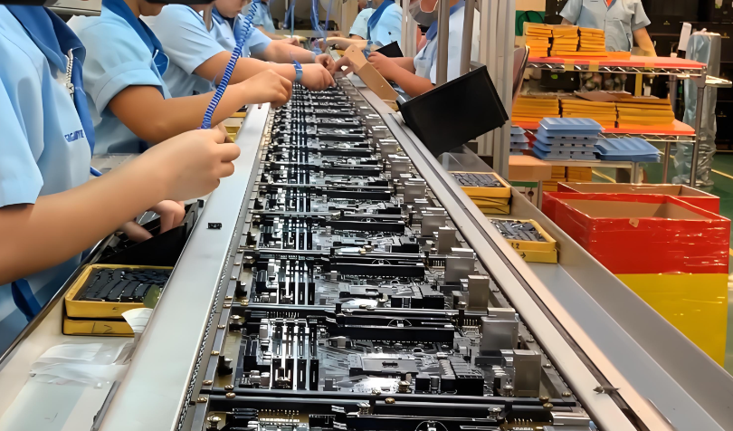
Assembly is a standard surface mount process with a few additions. The board is usually thin, which means it needs support during printing and reflow, and thin boards warp more readily, so a symmetric stack-up is preferred. Large components are best placed on the top side where they can be inspected and where the board can be supported beneath them. Our design release checklist covers the items to confirm before releasing the layout.
Test and Validation
Bench testing covers the power rails, the sensor outputs and the radio link, but the behaviour that matters only appears in flight. The qualification programme therefore includes a hover test with the logging enabled, a check of the inertial data for vibration-induced noise, a temperature measurement on the speed controllers and the regulators under load, and a range check on the radio and video links.
Failures found at this stage usually trace back to three causes: a ground return shared between the motor supply and the sensors, a thermal assumption that ignored the lack of airflow around a sealed component, or a mechanical arrangement that allowed the board to move relative to the frame. Each of these can be corrected in a layout revision, and each is far cheaper to correct before the platform is in production.
FAQ
How many layers does a drone PCB need? Four layers is the practical minimum for a board with a flight controller, sensors and a radio, because the reference plane and the power distribution both need their own area. Small toy-grade boards can work on two layers with careful routing.
Should the flight controller be on the main board? Often it is, which saves weight and connectors, but the sensors then have to tolerate the vibration of the whole board. Separating the sensor section onto its own small board with a damping mount can be better where the flight performance demands it.
Why do drone boards fail after a crash even when nothing looks broken? The damage is usually a cracked solder joint or a fractured ceramic capacitor that still makes contact when the board is cold and at rest. X-ray inspection and a continuity check under flex are the ways to find it.