Drone PCB Design: Weight, Vibration and Power
A drone is a flying vibration environment with a battery attached. Every design decision on its board is weighed against mass, and the board must simultaneously survive continuous vibration, deliver tens of amps to the motors and keep a radio link working next to switching regulators.
What Makes a Drone PCB Different
The constraints arrive together rather than separately. Weight limits the board area and the copper available for heat spreading. Vibration affects every solder joint and every connector. High motor currents create magnetic fields and ground noise, and the radio sits centimetres away from the power stage.
A flight controller board therefore concentrates the hardest parts of several disciplines into a small area, and the layout has to satisfy them without the luxury of extra space.
Weight Reduction Without Losing Rigidity
Weight is reduced by removing material rather than by shrinking circuitry. Thin laminates, fewer layers where routing allows and careful placement that shortens traces all contribute, and cut-outs in non-critical areas remove grams that multiply across a whole assembly.
Rigidity matters as much as mass. A board that flexes under vibration fatigues its solder joints, so the mechanical mounting and the stiffening effect of the enclosure are part of the design. Where the board carries an inertial sensor, flexing also corrupts the measurement.
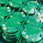
<img src="https://www.gopcba.com/wp-content/uploads/2026/09/49-2.jpg" alt="Flight controller drone PCB with motor power distribution” />
Vibration Resistance and Shock Survival
Vibration fails assemblies in three ways: solder joint fatigue, connector fretting and component resonance. Large components such as electrolytic capacitors and connectors are the usual casualties because their mass loads a small joint.
Solutions are mechanical before they are electrical. Choose components with low mass or add adhesive to large parts, avoid mounting heavy components in the middle of an unsupported span, and place connectors where the board is stiff or where the housing supports them. Where the assembly will see hard landings, the mounting scheme should allow the frame to absorb energy rather than the board.
Power Distribution and Motor Currents
Motor current can reach tens of amps during acceleration, and it flows in fast switching edges. The distribution network must present low inductance to the electronic speed controllers, which means wide copper, short loops and a capacitor bank placed physically close to the switching devices.
Current sensing and shunt placement belong on the same list. A shunt that shares a return path with other circuits produces a measurement error that changes with load, and the error appears as unstable motor behaviour rather than as an obvious fault.
IMU Placement and Noise
The inertial measurement unit must be placed where it sees mechanical motion rather than board flex, and where it is isolated from thermal gradients. Placing it near the power stage introduces both vibration transmitted through copper and a temperature offset that drifts as the motors heat.
Electrically, the accelerometer and gyroscope are sensitive to supply noise and to magnetic fields. Keeping them away from inductors and high-current loops is more effective than any amount of filtering added afterward.

RF Interference and Antenna Placement
The radio link shares the board with switching regulators, which is a difficult combination because switching harmonics can fall inside the receiver band. The practical measures are distance, grounding and filtering: keep the antenna feed away from the power stage, keep the return path under the feed continuous and filter the supply to the radio module.
Antenna placement is also mechanical. The radiating element needs clearance from copper and from the battery, and the ground plane dimensions around it affect tuning. A layout that ignores this produces a link that works on the bench and fails at range.
Grounding Strategy for Mixed Loads
A single continuous ground plane with careful placement is usually better than splitting, provided the high-current returns are kept away from sensitive circuitry. The motor returns should be grouped and routed so that their current does not flow beneath the inertial sensor or the radio.
Via stitching around the power stage and under the radio module helps contain the fields and provides a low-impedance return for high-frequency current. Where a split is unavoidable, the two regions must meet at one point, as described in the guidance on ground and power trace planning.
Thermal Design in a Sealed Frame
There is no airflow inside a drone frame, and the electronic speed controllers dissipate real power. Copper area, thermal vias down to the ground plane and a mechanical path to the frame are the available tools, and all three have to be designed in rather than added later.
The battery also heats the enclosure. Placing temperature-sensitive components away from the battery and the regulators, and compensating the sensor readings where they cannot be moved, is part of making the flight controller behave consistently across a flight.
Testing and Validation
Validation is mechanical as much as electrical. A vibration table test at the specified profile reveals joint fatigue that functional testing never sees, and repeated drop or shock testing confirms the mounting scheme.
Electrically, the design should be tested at full motor current with the radio active, because that combination is where interference appears. Measuring the supply rails with a scope at the sensor and radio pins shows the noise that matters, rather than the noise at the regulator output. Where fine-pitch devices and vias are combined in a small area, reviewing escape routing and fanout before layout saves a full re-route later.
Choosing Layers, Materials and Copper Weight
Flight hardware tends to settle on a small set of standard choices. A high Tg laminate is preferred because the board may run warm inside a sealed frame, and it also resists the thermal cycling that follows repeated flights. Four to six layers covers most flight controllers, with the inner layers used for ground and power rather than for routing.
Copper weight is usually kept at one ounce on signal layers and raised only where motor current demands it. Heavy copper everywhere adds mass and makes fine routing harder without a corresponding benefit, so the power stage and the sensitive digital section are treated as separate design problems on the same board.
Surface finish follows the assembly process. A flat finish is needed for the fine-pitch devices on the controller, while the power stage tolerates a coarser one. Where a single finish must serve both, a planar gold finish over nickel is the usual compromise, and the assembly profile should be validated on the actual stackup before production.
FAQ
How many layers does a flight controller need? Most designs settle between four and six, with additional layers used for a continuous ground plane and for power distribution rather than for more routing. The plane is what makes the dense mixed-signal layout work.
Can I use a rigid-flex board to save weight? Sometimes, particularly where the board must fold into a frame. The construction adds cost and its own mechanical limits, so it is worth comparing against a separate board plus a cable, as discussed in flexible interconnect selection.
Why does my IMU drift after a flight? Drift that appears only when the motors run usually indicates thermal coupling or magnetic interference rather than a sensor fault. Check the placement relative to the power stage and the current loops before changing the sensor or the filtering.