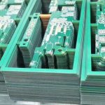
Ultra-Small Passives: Building Boards With 008004 Parts
Each generation of portable and wearable electronics moves a step further in the same direction: less space, less thickness, more function. The component families follow, and the smallest passives now in volume production are around two tenths of a millimetre in length and one tenth in width. At that size the part is difficult to see without magnification, and the challenges it creates are not simply a scaled-up version of the ones that came before.
A board that carries an ultra-small passive is therefore a different manufacturing problem, and the differences are worth understanding before the design is fixed rather than after the first batch has been built.
What Changes at This Size
The first change is that the part becomes comparable in scale to the accuracy of the equipment placing it. Where a device is hundreds of micrometres across, an offset of tens of micrometres is tolerable; where it is a fraction of that, the same offset consumes a large share of the available tolerance and the joint formed depends on the deposit rather than on the placement.
The second change concerns handling. These parts are supplied in very small reels and the quantity per reel is high, which is convenient for production but unforgiving in setup: a spilled feeder or a mis-picked part is invisible, and the pick position has to be maintained accurately throughout the run.
The third change is in inspection. A joint on a part this small occupies a few thousandths of a square millimetre, and its appearance is at the limit of what optical systems resolve reliably, which shifts the emphasis from inspecting the joint to controlling the process that produces it.
Placement Accuracy and Force
Placement accuracy has to improve in proportion, and the published tolerance of a machine is a description of its best behaviour rather than its daily one. What matters in practice is the accuracy maintained across a whole panel, at production speed, over a shift.
Force control becomes a separate concern. The nozzle holds the part by vacuum and releases it onto the deposit, and the pressure involved has to be small enough not to damage a body that is only a fraction of a millimetre thick. A nozzle that is too large will pick up neighbouring parts; one that is too small will lose the part in transit. The nozzle selection and the vacuum profile are therefore part of the process rather than accessories to it.
Vision is the third element. A machine recognises the part before placing it, and recognition depends on contrast and on the optical resolution available. Where the part is small and low in contrast, recognition becomes less reliable, and a machine that hesitates places inconsistently.

Paste Volume as the Deciding Variable
At this scale the printed deposit is a large fraction of the joint, and the outcome is decided before the part is placed. Too much paste produces bridging between adjacent terminations on a part whose ends are a tenth of a millimetre apart; too little leaves a joint that is thin, weak or open.
The stencil therefore has to be designed for the pads rather than derived from a generic rule. Aperture size, the wall finish of the opening and the way the paste releases from it all affect the volume transferred, and the area ratio of the aperture sets a practical limit that cannot be overcome by adjusting the printer.
Support belongs to the same discussion. A board that flexes by a few tens of micrometres under the squeegee will print a different volume across its length, and at this scale that variation is enough to change the result. Vacuum support, a flat tooling plate and a consistent board thickness are what keep the deposit even.
The Thermal Profile and Mixed Sizes
Small parts have little thermal mass, so they reach temperature far sooner than the larger components beside them. A profile chosen for a heavy connector will overheat the smallest devices, and a profile chosen for them will leave the larger joints insufficient. Where a board mixes a very small passive with a device of significant mass, the process window narrows from both directions.
That is the argument for measuring the profile on the actual assembly rather than applying a standard one. Where the window proves difficult, the usual remedies are a slower ramp, a longer soak and, in the most demanding cases, an atmosphere with reduced oxygen to protect the surfaces while the profile is extended.
<img src="https://www.gopcba.com/wp-content/uploads/2026/05/smart-logistic-PCBA.jpg" alt="paste deposit inspection for ultra-small passive assembly” />
Inspection Limits and What to Substitute
Optical inspection retains its value for the assembly as a whole, confirming that the parts are present, in the right place and correctly oriented, but its ability to judge a joint at this scale is limited and prone to false calls in both directions.
The compensating controls are the ones applied earlier in the process: measurement of the paste deposit, verification of the first article at magnification, and the discipline of a process that has been established and recorded rather than adjusted at the machine. Where electrical verification is possible, a test of the circuit’s behaviour is often more informative than an image of the joint.
Where the product warrants it, X-ray can confirm the presence of a joint and detect voids, though its resolution at this scale is limited compared with its use on larger packages.
Board Design for Very Small Parts
Some of the constraints are fixed in the layout rather than at the machine, and they are cheaper to accommodate in the drawing than in the process.
The pads have to be sized for the part rather than inherited from a larger footprint, and the spacing between the two terminations of a device determines how much paste can be printed before the risk of bridging appears. Copper balance matters as well, because a trace that conducts heat away from one end of the part and not the other produces an uneven joint and, on the smallest sizes, a part that stands up at reflow.
Placement density belongs in the same consideration. Parts are easiest to place where there is room for the nozzle to approach without fouling a neighbour, and a layout that clusters them tightly for the sake of board area may make the process more difficult than the space saved is worth.
The surrounding components also set the profile. Where a large device sits beside a very small one, the thermal difference between them cannot be removed, only managed, and the position of the small part relative to the heavy one is a design decision that has a thermal consequence.
Where These Components Belong
The parts are used where space and thickness are at a premium and the quantity justifies the process: wearable devices and earbuds, small medical instruments, dense modules in premium products, and applications where weight matters.
For most products, the previous generations of passives remain appropriate and easier to build. The decision to move to the smallest available part should be made for a functional reason, since it exchanges board area against process margin and inspection confidence.
Where the decision has been made, the data matters more than usual: accurate pad geometry, a stencil designed for it, a stated component class and an identified set of positions that need particular attention. The operations involved are SMT assembly, with verification through PCBA testing and the process controls described under quality management.
FAQ
Can the smallest passives be placed on ordinary equipment? Placement is possible, but the result depends on paste volume, nozzle selection and force control, which is why the process matters more than the machine’s headline tolerance.
Why is paste volume so critical for these parts? Because the deposit is a large proportion of the joint, and the distance between the two terminations is small enough that a slight excess creates a bridge.
How should they be inspected? By controlling the deposit and verifying the first article at magnification, rather than relying on optical inspection to judge joints at this scale.