Vacuum Reflow Soldering for Solder Void Reduction on BGA
A void is a bubble of gas trapped inside a solder joint, and in most joints it is harmless. In a joint that has to conduct heat, however, a void reduces the area through which the heat can pass, and a large void under a thermal pad can raise the junction temperature of a device by more than the design allows. Vacuum reflow soldering exists to remove those bubbles while the solder is still liquid, and it is now a standard process for power electronics and for large area thermal joints.
Why Voids Form
Gas can enter a joint from several sources. Flux volatilises as it is heated and produces vapour, air can be trapped as the paste melts and the surfaces come together, and the oxide or the plating can release gas at temperature. Whatever the source, the gas has to escape through the molten solder before the joint solidifies and closes the path.
Escape is easier in a small joint with a short path to the edge and harder in a large, flat joint where the gas has to travel a long distance through viscous liquid metal. That is why voids are rare in a fine pitch signal joint and common under a large thermal pad or a power package, where the gas has the greatest distance to travel.
Where Voids Matter
The consequences of a void depend on the function of the joint. In a signal joint a void reduces the cross section slightly and changes nothing important. In a joint that carries current the void concentrates the current and raises the local temperature, and in a thermal joint it reduces the heat flow in exactly the place where the design assumed a solid connection.
The critical cases are therefore power devices, thermal pads, large area joints and any application where the joint is part of the thermal path. In those cases the void content becomes a specification with a limit on the total void area and often a separate limit on the largest single void, because one large bubble is worse than several small ones.

How Vacuum Reflow Works
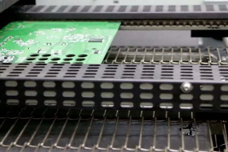
The principle is simple. The assembly is reflowed in a chamber whose pressure can be reduced, and while the solder is molten the pressure is lowered so that the gas bubbles expand and rise out of the joint. The pressure is then restored, and the joint solidifies as the board cools.
The technique works because the reduction in pressure allows a bubble that was previously stable to grow and to break through the surface of the molten solder. The window in which the vacuum can be applied is limited to the time the alloy remains liquid, so the process has to be integrated with the thermal profile rather than added to the end of it.
<img src="https://www.gopcba.com/wp-content/uploads/2026/08/through-hole-assembly-process-1536×640-1.webp" alt="X-ray image showing solder void reduction under a thermal pad” />
Chamber Pressure and Profile
The profile has three additional parameters compared with a conventional oven: the pressure that is reached, the moment at which the vacuum is applied and the time spent at low pressure. Each of them affects the result, and the three interact with the thermal profile that produces the joint in the first place.
The pressure is normally expressed as an absolute value, and lower pressures give more complete evacuation up to the point where solder is ejected from the joint or the paste is disturbed. The vacuum should be applied when the solder is fully molten and the joint has formed, not while the paste is still releasing its solvent, and the dwell should be long enough for the bubbles to travel to the surface.
Effects on Solder and Components
The process changes more than the void content. A joint formed under vacuum can have a different surface appearance, because solder that has been disturbed by the expanding bubbles solidifies with a slightly different topography. The fillet shape can also change, and the inspection criteria may need to be adjusted accordingly.
Components see the vacuum as a mechanical environment as well as a thermal one. A part with an internal cavity, a sealed package or a flexible membrane may be affected by the pressure change, and a large electrolytic capacitor that would survive a conventional profile should be assessed before it is run in a vacuum process.
Void Measurement and Criteria
Voids are measured by X-ray, and the result is expressed as a percentage of the joint area together with the size of the largest void. The measurement method matters because a different threshold in the image analysis will produce a different number for the same joint, so the criterion should define how the measurement is made as well as what limit applies.
Acceptance criteria should be set from the function of the joint. A thermal pad that has to conduct a defined power has a calculable requirement, while a signal joint needs no limit at all. The techniques used for the measurement are compared in the guide to X-ray and AOI inspection.
Verification and Process Records
Verification starts with a design of experiment that relates the pressure and the dwell to the measured void content, followed by a confirmation on the production assembly. Once the window is known, the process is controlled by recording the profile and the chamber pressure for every board, together with a periodic X-ray check.
Drift in the process usually appears as a gradual rise in void content rather than as a sudden failure, and the cause is often a small leak, a worn seal or a change in the paste. The records are what allow the drift to be seen before the joints fail a thermal requirement, and the general approach to these failures is described in the guide to solder defects and board failures.
Equipment and Cost Considerations
Vacuum reflow equipment costs more than a conventional oven, and the cycle is longer because the chamber has to be evacuated and refilled. The throughput of the line therefore falls, and the cost per board rises, which means the process should be applied where it produces a measurable benefit.
The benefit is measurable when the void content determines the thermal performance of the product. Where that is the case, the calculation is straightforward: the reduction in junction temperature, or the increase in allowable power, against the additional process cost. Where it is not the case, the investment is difficult to justify.
When Vacuum Is Not the Answer
Voids are produced by the paste, the profile and the surfaces as well as by the absence of a vacuum. A board with an oxidised pad, an unsuitable paste or a profile that drives the solvent off too quickly will produce voids that no amount of evacuation will remove, because the gas is being generated faster than it can escape.
The foundation should therefore be correct before vacuum is considered, because a process that is failing at the basics will not be rescued by a chamber. A sound paste, a clean surface and a profile that allows the volatiles to leave will reduce the void content on their own, and vacuum should be the final step that removes what remains rather than a substitute for them. The thermal requirements that often drive the decision are described in the guide to thermal management design.
FAQ
What void content can vacuum reflow achieve? The result depends on the joint size, the paste and the profile, and it is normally expressed as a target range rather than a single figure. A significant reduction compared with a conventional process is achievable, and the exact limit should be set from the thermal requirement of the product.
Does vacuum reflow damage components? It can affect parts with internal cavities or sealed volumes, because they experience a pressure change while they are hot. Those parts should be assessed individually, and the profile should be arranged so that the pressure change happens when the assembly is at the lowest practical temperature.
Is vacuum always necessary for a thermal pad? Not always. A well designed pad with a suitable paste and a correct profile may meet its thermal requirement without vacuum. The decision should be made from a measured void content and a thermal calculation rather than from a general preference.