


PCB Assembly Explained: Process, Types, and Defects
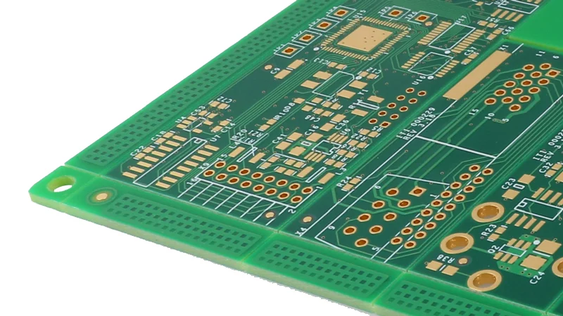
PCB assembly is the step where components are soldered onto a bare circuit board. The bare board carries copper traces and pads, but it does nothing until parts are attached. Assembly turns that empty board into a working electronic product. Buyers and engineers both need a clear view of this stage. It decides cost, yield, and how the product behaves in the field.
Components fall into two broad groups. Passive parts such as resistors and capacitors do not add gain to a signal. Active parts such as transistors and ICs can amplify or switch. Both groups appear on most boards, and both must be placed and soldered correctly. The mix of parts on your board shapes the process you need. It also shapes the inspection and test plan that follows.
Assembly can be done by hand or by machine. Most production work uses automated equipment because it is faster and more consistent. Manual work still has a place in prototypes and repair. The choice depends on volume, part mix, and how tight the tolerances are. A good supplier will match the method to the job rather than force one approach.
Two main technologies dominate the field: through-hole and surface mount. Through-hole inserts leads through drilled holes and solders them. Surface mount places parts directly onto pads on the board surface. Many modern products use surface mount, but through-hole remains common for power and mechanical parts. Mixed boards use both, and that mix changes how the line is set up. Understanding the difference helps you read a quote and ask better questions.
Through-Hole Technology Basics
Through-hole technology is the older method. Component leads pass through pre-drilled holes in the board. Solder then joins the lead to the pad and connects layers. Automatic insertion machines place most parts, using a program loaded into the controller. The board then passes over a molten solder wave for a few seconds. That wave soldering step forms the joints on the underside.
Two lead styles are common. Axial leads run along the body axis, and radial leads run perpendicular to it. Each style needs its own forming and insertion setup. After soldering, the board goes through electrical testing to find opens and shorts. Testers check resistance between circuit nodes while the board is powered. This catches many faults, but it does not catch every visual defect.
Through-hole parts offer strong mechanical connections. Leads pass through the board and are soldered on the far side. That makes the joint resistant to vibration and physical stress. Equipment that sees frequent handling or shock often keeps through-hole parts for this reason. The joint holds up where a surface pad might lift.
Repair is also simpler with through-hole parts. A technician can desolder and replace a part without special rework gear in many cases. That helps during prototyping and testing. Power handling is another strength, since larger parts can carry more current. Transistors, transformers, and regulators often stay through-hole for this reason. The tradeoff is size, because these parts take more board area.
Surface Mount Technology Basics
Surface mount technology places parts directly onto pads on the board surface. Solder paste holds the part in place before reflow. This method allows much smaller spacing between parts. It also supports smaller packages and finer leads. The push for smaller devices drove wide adoption of this method. Most consumer and industrial boards now rely on it.
Surface mount supports high pin counts on a small area. More connections fit into less space, which allows greater functionality per board. Shorter connection paths also help high-frequency designs. That matters as signal speeds rise and boards shrink. The method fits dense, compact layouts well.
Not every design can go fully surface mount. Power sections often keep through-hole parts for mechanical strength. Transformers and large capacitors may need the robust joint that through-hole gives. A mixed board is common in power electronics and industrial control. The supplier must plan both processes on one line. That planning affects cost and lead time, so raise it early.
Solder Paste Printing
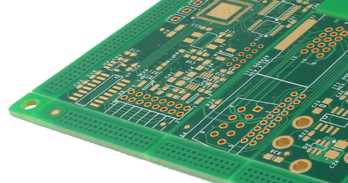
Printing is the first step in the surface mount flow. A stencil deposits solder paste onto the board pads. A squeegee moves across the metal stencil and pushes paste through the openings. The paste volume must match the pad and the part. Too much paste causes bridges, and too little causes opens. Print quality sets the base for everything that follows.
Most industries now use lead-free paste to meet hazardous substance rules. SAC paste, an alloy of tin, silver, and copper, is common. It needs a higher reflow temperature than older tin-lead paste. That affects the oven profile and the parts you can use. Check that your components are rated for the peak temperature. Paste storage and shelf life also matter for consistent printing.
Stencil design drives print quality. Aperture size and shape control how much paste lands on each pad. Fine-pitch parts need careful aperture work to avoid bridging. The stencil must also be cleaned on a set schedule. Paste left in apertures dries and blocks the next print. A supplier that tracks these details will show fewer print defects over a run.
Placement and Reflow
A pick-and-place machine moves parts from reels or trays onto the board. It follows a program with fixed positions and rotations. The tackiness of the paste holds each part until reflow. Placement accuracy matters more as parts shrink. A small offset that was fine on a large part can cause a defect on a fine-pitch one. Program verification before the run is worth the time.
The board then enters a reflow oven. It is preheated below the peak temperature so the flux can activate. The temperature then climbs to the peak needed to melt the paste. After the peak, the board cools to solidify the joints. Heating usually comes from infrared radiation or forced hot air. The profile must suit both the paste and the parts.
Reflow profile control is central to yield. Too fast a ramp can cause thermal shock. Too little heat leaves incomplete joints. Multiple heating zones give finer control across the board. Larger boards and heavy parts need more careful profiling. Ask for the profile record with the lot, because it shows what the oven actually did.
Inspection and Test Coverage
Manual inspection is slow and depends on human judgment. Automated optical inspection gives faster and more consistent results. It compares the board against a known good image and flags differences. This catches many defects that electrical test cannot see. Missing parts, shifted parts, and poor joints often show up here first.
Electrical test comes after inspection. In-circuit test uses a fixture with many probes, like a bed of nails. It checks each net for opens, shorts, and part values. Flying probe test uses moving probes instead of a fixture. It costs less to set up but is generally slower. The right choice depends on volume and board complexity.
Test coverage should be agreed before production. Some faults only appear under power or over time. Functional test and burn-in add confidence for critical products. Ask what each test step covers and what it leaves open. A clear test plan protects both sides. It also gives you records to compare across lots. For deeper process control, see our notes on quality management.
Common Defects and Fixes
Solder bridging is a frequent defect. Excess paste or a poor profile lets solder join adjacent pads. That creates a short and can fail the board. Correct paste volume and a tuned profile reduce the risk. Stencil cleaning and aperture design also play a part. A supplier should track bridge rates and act on the trend.
Component misalignment happens when a part shifts during reflow. Uneven paste or a poor placement can cause it. The result may be an open or a short. Even paste spread and accurate machine programming help prevent it. As parts shrink, alignment tolerance tightens. This is one reason fine-pitch work needs careful setup.
Poor solder wetting appears when solder does not bond to the pad. Oxidation on pads or leads is a common cause. Heat speeds oxidation, so nitrogen in the oven can help. Proper cleaning and paste control also matter. Check paste dates, storage, and shelf life. Wetting problems often trace back to material handling, not the oven.
Tombstoning lifts one end of a part during reflow. Uneven melting or solidifying forces cause it. The part stands upright on one end and fails. A balanced thermal profile helps keep both ends even. Stencil apertures should deposit equal paste on both sides. Small parts are most exposed, so review the design and the print together.
Buyer Checks Before Release
Material shortages can stall a build. Causes include raw material limits, rules, discontinued parts, and supplier closures. A practical plan lists approved alternates for key parts. It also names a backup source for the assembly itself. Review that plan before you place the order. For sourcing help, see component procurement.
Process control needs a real system, not a promise. Reflow temperature must stay in its window to avoid defects. Multi-zone ovens give tighter control on complex boards. Placement sequence and travel path affect throughput. These details decide whether a line meets its schedule. Ask how the supplier measures and records them.
Capacity planning matters for repeat orders. Overall equipment effectiveness, machine flexibility, and changeover time all shape output. Placement is often the bottleneck on a surface mount line. Optimizing the sequence and path for each product helps. So does reducing setup time between lots. A supplier that tracks these numbers can quote a date it can keep.
Documentation is as important as hardware. The lot record should show the program, the paste and part reels, the operator, and the inspection result. When a field return arrives months later, that record is the fastest path to the cause. Ask for these records as a routine part of each order. It is a fair request, and good factories keep them anyway. For layout support, see PCB design and layout.
Prototypes are the cheapest place to find problems. A small first batch reveals pad issues, part tolerances, and process behavior. Fixing these before volume saves rework later. Treat the first article as part of the project, not an extra cost. Teams that invest here usually reach volume faster. They also see fewer surprises on the line.
When you compare suppliers, look past the unit price. Process controls, inspection gear, sourcing, and communication decide the real cost. A partner that reviews files early and reports risks honestly is cheaper over time. For larger builds, review our high-volume PCB assembly notes. For a single source across sourcing and build, consider turnkey PCB assembly. The takeaway is simple: agree the process, the inspection, and the records before the first board is built.