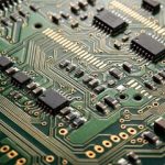
Heavy Copper PCB Manufacturing and Design Guide
What Is a Heavy Copper PCB?
A Heavy Copper PCB is a printed circuit board manufactured with significantly thicker copper layers than those used in conventional PCBs. Standard PCBs commonly use copper weights of approximately 1–2 oz, while heavy copper designs typically use 3 oz or more, depending on the electrical and mechanical requirements of the application.

The increased copper thickness provides higher current-carrying capacity, improved heat dissipation, lower electrical resistance, and greater mechanical robustness. These characteristics make heavy copper boards particularly suitable for power electronics, battery systems, industrial controls, automotive electronics, power supplies, and other applications where high current and thermal performance are critical.
For projects that require both high-current performance and reliable production, integrating Heavy Copper PCB Manufacturing with appropriate material selection, copper weight, trace geometry, via design, and thermal management is essential.
For complete board production and assembly requirements, see our PCB Manufacturing Services for an overview of available PCB fabrication capabilities.
Why Use a Heavy Copper PCB?
Copper has excellent electrical and thermal conductivity. Increasing the copper thickness reduces conductor resistance and allows PCB traces to carry higher currents without excessive temperature rise.
A thicker copper layer can also provide a more effective thermal path between high-power components and the PCB structure. This can help distribute heat over a larger area and reduce localized thermal stress.
However, copper thickness should not be increased simply because more copper is available. A successful Heavy Copper PCB Design must balance current requirements, trace width, temperature rise, layer structure, dielectric thickness, via construction, manufacturing tolerances, and overall board cost.
Heavy copper technology is therefore especially valuable when a conventional PCB cannot provide sufficient current capacity, thermal performance, or mechanical strength.
Advantages of Heavy Copper PCBs
Higher Current-Carrying Capacity
One of the primary benefits of a High Current PCB is its ability to accommodate higher electrical loads.
Thicker copper conductors have a larger cross-sectional area, which reduces electrical resistance and allows more current to flow with lower power loss. This makes heavy copper technology suitable for:
- Power supplies
- Battery management systems
- Motor controllers
- Power converters
- Industrial control equipment
- Automotive power electronics
- Renewable energy systems
The actual allowable current depends on copper thickness, trace width, permissible temperature rise, board construction, and operating environment. These parameters should therefore be evaluated together during PCB design.
Improved Thermal Management
Heavy copper can improve heat spreading within the PCB and provide a more effective thermal path for high-power circuits.
Power components such as MOSFETs, IGBTs, rectifiers, regulators, and high-current connectors can generate significant heat during operation. A properly engineered heavy copper structure helps distribute this thermal energy and reduce localized hot spots.
For more complex PCBA requirements, our PCB Assembly Services support heavy copper PCB assembly as well as rigid, flexible, rigid-flex, multilayer, high-TG, and other PCB structures.
Lower Electrical Resistance
The resistance of a PCB conductor decreases as its copper cross-sectional area increases. Heavy copper therefore helps reduce I²R losses in high-current paths.
Lower conductor resistance can provide several practical benefits:
- Reduced voltage drop
- Lower power dissipation
- Improved electrical efficiency
- Reduced conductor heating
- Better performance in high-load circuits
This is particularly important in power conversion and energy-management applications where even small electrical losses can become significant during continuous operation.
Greater Mechanical Strength
Thicker copper can contribute to the overall robustness of a PCB, particularly around high-current terminals, connectors, mounting areas, and other mechanically demanding regions.
Heavy copper structures are therefore useful in equipment exposed to vibration, thermal cycling, mechanical stress, and demanding industrial operating conditions.
Improved Thermal and Electrical Reliability
A properly designed Power PCB can provide better resistance to thermal stress and electrical overload than a conventional copper-weight design.
Heavy copper is commonly considered for equipment that must operate continuously or under demanding load conditions, including industrial power systems, automotive electronics, energy storage systems, telecommunications equipment, and high-power control electronics.
Heavy Copper PCB Applications
Power Electronics
Power electronics is one of the most common application areas for heavy copper circuit boards.
Typical applications include:
- AC/DC power supplies
- DC/DC converters
- Inverters
- Motor drives
- Power distribution systems
- Industrial power controllers
The higher copper weight allows designers to create robust current paths while maintaining controlled thermal performance.
Automotive Electronics
Electric vehicles and modern automotive systems contain numerous high-current electronic circuits.
Heavy copper PCBs can be used in applications such as:
- Battery management systems
- Motor control
- DC/DC converters
- On-board chargers
- Power distribution
- Automotive power modules
Industrial Equipment
Industrial control equipment often operates under high electrical loads and demanding environmental conditions.
Heavy copper boards can support industrial automation, motor controllers, power supplies, welding equipment, energy systems, and other high-power electronic equipment.
Renewable Energy and Energy Storage
Solar power systems, battery storage equipment, and energy conversion systems frequently require high-current PCB structures.
Heavy copper technology can be used for:
- Solar inverters
- Battery management systems
- Energy storage systems
- Power conversion equipment
- Charging systems
Heavy Copper PCB Design Considerations
Copper Weight
Copper weight is one of the most important parameters in heavy copper PCB design.
Typical designs may use 3 oz, 4 oz, 5 oz, 6 oz, or even higher copper weights depending on the application. The required copper thickness should be determined according to current, temperature rise, available board space, and manufacturing capability.
Trace Width and Spacing
Higher copper weights generally require greater consideration of trace width and spacing.
As copper thickness increases, achieving fine line geometries becomes more challenging. Designers should therefore work with the PCB manufacturer early in the development process to ensure the proposed stack-up and conductor geometry are manufacturable.
Thermal Management
High-current PCB layouts should consider both electrical and thermal performance.
Designers may use:
- Wider copper areas
- Copper pours
- Thermal vias
- Large component pads
- Dedicated heat-spreading layers
- Appropriate substrate materials
- Optimized component placement
The objective is to create a controlled thermal path from heat-generating components into the PCB and surrounding structure.
Via Design
Vias carrying high current require careful engineering. Conventional small vias may not provide sufficient current capacity for demanding power circuits.
Depending on the application, designers may use larger vias, multiple parallel vias, via arrays, or other enhanced via structures to improve electrical and thermal performance.
Layer Stack-Up
Heavy copper may be applied to external layers, internal layers, or both.
The stack-up should consider:
- Number of layers
- Copper thickness
- Dielectric thickness
- Impedance requirements
- Thermal requirements
- Current distribution
- Mechanical thickness
- Manufacturing limitations
A well-designed stack-up can help balance electrical performance with manufacturability and cost.
Heavy Copper PCB Manufacturing Capabilities
Heavy copper PCB production requires tighter process control than standard PCB fabrication because thicker copper affects etching, plating, line definition, hole filling, lamination, and overall dimensional control.
Typical manufacturing considerations include:
| Parameter | Typical Capability / Requirement |
|---|---|
| PCB Material | Standard FR-4 or High-Tg FR-4 |
| Standard Tg | Approximately 140°C |
| High-Tg Material | Approximately 170°C |
| Copper Weight | 3 oz and above depending on design |
| Maximum Finished Outer Copper | Up to approximately 15 oz* |
| Maximum Inner-Layer Copper | Up to approximately 12 oz* |
| Board Thickness | Approximately 0.6–6.0 mm* |
| Typical Fabrication Lead Time | Approximately 5–7 working days* |
| Expedited Delivery | Project dependent* |
*Actual capability depends on board structure, copper weight, layer count, dimensions, line/space requirements, surface finish, and production quantity. Engineering review is recommended before production.
For projects combining heavy copper structures with component assembly, Heavy Copper PCB Assembly can be integrated into a complete PCB manufacturing and assembly workflow.
Heavy Copper PCB Manufacturing Process
1. Engineering Review
The manufacturing process begins with an engineering review of the Gerber files, stack-up, copper weights, board dimensions, drill data, impedance requirements, and other technical specifications.
Design-for-manufacturing analysis can identify potential problems before fabrication begins.
2. Material Selection
FR-4 is widely used for heavy copper PCBs, while high-Tg materials may be selected for applications exposed to higher temperatures or demanding thermal conditions.
Material selection should consider operating temperature, dielectric performance, mechanical requirements, and long-term reliability.
3. Inner-Layer Fabrication
For multilayer heavy copper PCBs, the inner copper layers are patterned and processed according to the specified circuit structure.
Thicker copper requires carefully controlled imaging and etching processes to achieve the required conductor geometry.
4. Lamination
The processed layers are laminated together under controlled temperature and pressure.
Heavy copper structures can introduce additional thermal and mechanical considerations during lamination, so the stack-up must be engineered appropriately.
5. Drilling and Plating
After lamination, holes are drilled and plated to establish electrical connections between layers.
For high-current applications, plated through-holes and vias must be designed to withstand the required electrical and thermal loads.
6. Outer-Layer Processing
The external circuit pattern is formed and plated according to the specified copper thickness.
The manufacturing process must balance copper thickness with the required line width and spacing.
7. Surface Finish and Solder Mask
The PCB can then receive its specified solder mask and surface finish.
The appropriate finish depends on component requirements, assembly technology, storage conditions, reliability expectations, and cost considerations.
8. Inspection and Testing
Final inspection may include dimensional inspection, electrical testing, visual inspection, copper thickness verification, and other customer-specific quality checks.
For assembled products, inspection can also include AOI, X-ray inspection, ICT, functional testing, and other verification methods.
Heavy Copper PCB vs. Standard PCB
| Feature | Standard PCB | Heavy Copper PCB |
|---|---|---|
| Copper Weight | Typically 1–2 oz | Typically 3 oz or higher |
| Current Capacity | Standard | High |
| Thermal Performance | Standard | Improved for high-current applications |
| Conductor Resistance | Higher | Lower with increased copper thickness |
| Mechanical Robustness | Standard | Generally higher |
| Manufacturing Complexity | Lower | Higher |
| Typical Applications | General electronics | Power and high-current electronics |
| Cost | Lower | Generally higher |
The best choice depends on the electrical load, thermal requirements, physical dimensions, production volume, and total product cost.
Design and Manufacturing Support
A reliable heavy copper project requires close coordination between PCB design and manufacturing engineering.
During the PCB Design and Layout stage, designers should provide complete information regarding:
- Required copper weight
- Layer stack-up
- Maximum current
- Temperature-rise limits
- Board dimensions
- Minimum trace width and spacing
- Hole and via requirements
- Surface finish
- Material requirements
- Impedance requirements
- Assembly requirements
Component sourcing can also influence the final manufacturing schedule. Using a structured Components Procurement process can help manage component availability, approved part numbers, and production planning.
For complex projects that combine SMT and through-hole components, Mixed Technology PCB Assembly can provide a suitable manufacturing approach for high-power and mechanically demanding electronic assemblies.
How to Choose a Heavy Copper PCB Manufacturer
When selecting a manufacturer for a Heavy Copper PCB, evaluate more than the maximum advertised copper weight.
Important factors include:
- Maximum finished copper thickness
- Internal and external copper capabilities
- Minimum trace width and spacing
- Maximum board dimensions
- Layer count
- Material options
- Via and plated-hole capabilities
- Thermal management experience
- Electrical testing
- Assembly capabilities
- Engineering support
- Production lead time
- Quality management
- Prototype and volume-production support
The manufacturer should also be able to review your design before production and identify potential fabrication risks.

Get a Heavy Copper PCB Quote
Heavy copper PCBs are an effective solution for high-current, high-power, and thermally demanding electronic applications. By increasing copper thickness and optimizing the PCB structure, designers can achieve improved current capacity, lower electrical losses, better heat distribution, and enhanced long-term reliability.
However, successful production depends on more than copper weight alone. Trace geometry, stack-up, material selection, thermal design, via construction, manufacturing tolerances, and assembly requirements must all be considered together.
If you are developing a high-current power supply, battery management system, motor controller, automotive electronics product, industrial control system, or energy-storage device, provide your Gerber files, stack-up, BOM, drawings, and technical requirements for engineering evaluation.
For project-specific requirements and manufacturing consultation, visit Contact Us to discuss your heavy copper PCB project.