In modern electronics development, moving from a circuit concept to a production-ready product requires more than a PCB design. Engineers need physical prototypes to verify electrical performance, component compatibility, firmware integration, thermal behavior, mechanical fit, and manufacturability before committing to mass production.
This is where Prototype PCB Assembly becomes essential.
Prototype PCB Assembly is the process of manufacturing and assembling a small quantity of printed circuit boards for engineering validation and product development. Unlike mass production, prototype assembly emphasizes speed, flexibility, design verification, engineering feedback, and rapid iteration.
A well-managed prototype process can identify problems before they become expensive production issues, helping companies shorten development cycles and reduce overall product risk.
What Is Prototype PCB Assembly?
Prototype PCB Assembly is the process of mounting and soldering electronic components onto a PCB in small quantities for testing and validation before large-scale production.
Prototype quantities can range from a few boards to several hundred units depending on the project and manufacturer.
The process normally includes:
PCB Fabrication → Component Procurement → SMT/THT Assembly → Inspection → Testing → Engineering Validation
Prototype PCBA allows engineers to evaluate:
- Circuit functionality
- Component compatibility
- Signal integrity
- Power integrity
- Thermal performance
- Firmware integration
- Mechanical fit
- EMI/EMC behavior
- Manufacturing feasibility
The objective is to create a reliable physical version of the design before scaling the product.
Why Is Prototype PCB Assembly Important?
Prototype assembly acts as a bridge between PCB Design and Mass Production.
Early Detection of Design Problems
A PCB may look correct in CAD software but still contain real-world issues.
Prototype testing can reveal:
- Incorrect component footprints
- Component placement problems
- Routing conflicts
- Insufficient clearances
- Power-distribution issues
- Signal-integrity problems
- Thermal hotspots
- Mechanical interference
Finding these problems during prototyping is generally much less expensive than discovering them after mass production has started.
Functional Validation
A prototype allows engineers to determine whether the circuit performs according to its intended specifications.
Testing can cover:
- Voltage
- Current
- Communication interfaces
- Sensor performance
- Processor operation
- Power management
- Firmware
- System functionality
Faster Design Iteration
Engineering teams can use prototype results to make improvements and quickly produce a revised board.
The development cycle becomes:
Design → Prototype → Test → Analyze → Revise → Prototype Again
This iterative process is particularly important for advanced electronics.
Lower Mass-Production Risk
Prototype assembly provides an opportunity to validate the complete manufacturing approach before high-volume production.
Engineers can evaluate:
- Component availability
- Assembly yield
- Soldering process
- Inspection coverage
- Testing procedures
- BOM stability
This helps reduce production surprises later.
Prototype PCB Assembly vs. Mass Production
| Factor | Prototype PCB Assembly | Mass PCB Assembly |
|---|---|---|
| Quantity | Small | Large |
| Main objective | Validation | Production |
| Design flexibility | Very high | Lower |
| Design changes | Frequent | Limited |
| Lead time | Short | Scheduled |
| Tooling | Minimal or limited | Highly optimized |
| Component sourcing | Flexible | Cost/availability optimized |
| Testing | Engineering-oriented | Production-oriented |
| Unit cost | Higher | Lower |
| Main priority | Speed and validation | Yield and scalability |
Prototype production should therefore not simply be considered a smaller version of mass production. The goals and manufacturing priorities are different.
Kingda Prototype PCB Assembly Services
Kingda provides rapid PCB prototyping and prototype PCBA services from prototype quantities through low-volume and volume production. Its published prototype service supports no minimum order quantity, SMT and through-hole assembly, fine-pitch components, component procurement, engineering support, AOI, X-ray, ICT, FCT, and FAI testing. (gopcba.com)
Kingda also states that prototype PCBA can normally be completed in 2–3 days, with an expedited option as fast as 12 hours, depending on project conditions and component readiness. (gopcba.com)
Kingda Prototype PCB Assembly Capabilities
Kingda’s published prototype capabilities include:
- Rigid PCB
- Flexible PCB
- Rigid-flex PCB
- SMT assembly
- Through-hole assembly
- Mixed assembly
- Fine-pitch components
- 01005 components
- BGA
- QFN
- X-ray inspection
- AOI
- ICT
- FCT
- FAI
- IC programming
- Lead-free/RoHS assembly (gopcba.com)
The company’s published capabilities list a minimum BGA pitch of 0.25 mm, minimum SMD component size of 01005, and IC assembly precision of approximately ±0.03 mm for its prototype services. (gopcba.com)
Quick-Turn Prototype PCB Assembly
Quick-Turn Prototype PCB Assembly is designed for projects where engineering teams cannot afford to wait several weeks between design iterations.
Kingda provides rapid prototype services with published lead times that vary according to product type and material readiness.
Its official prototype page currently lists:
| Production Type | Published Lead Time |
|---|---|
| Prototype | Normal 2–3 days |
| Expedited Prototype | As fast as 12 hours |
| Low Volume | Normal 3–5 days |
| Expedited Low Volume | 24–48 hours |
| Volume Production | 5–7 days |
Actual delivery time depends on PCB complexity, component availability, assembly requirements, testing, and logistics. (gopcba.com)
Advantages of Quick-Turn Prototype PCB Assembly
Faster Product Development
Rapid prototype assembly allows engineers to move from design files to physical hardware faster.
This can shorten:
Design → Assembly → Testing → Revision
cycles.
Faster Design Validation
Engineering teams can quickly verify:
- Electrical functionality
- Signal integrity
- Power integrity
- Thermal behavior
- Mechanical compatibility
Reduced Development Risk
Identifying a design problem before mass production can prevent expensive tooling, material waste, and large-scale rework.
Faster Time to Market
Companies can complete additional engineering iterations within the same development period.
This can be particularly valuable for:
- Startups
- R&D teams
- AI hardware
- IoT products
- Medical devices
- Automotive electronics
- Industrial equipment
Prototype PCB Assembly Process
A professional prototype manufacturing process should maintain the same attention to quality as production manufacturing while allowing greater engineering flexibility.
Step 1: Design and Documentation Review
The process begins with the design package.
Typical files include:
- Gerber files
- BOM
- Pick-and-place files
- Assembly drawings
- Schematic
- PCB stack-up
- Testing requirements
Kingda provides engineering design review and DFM support before production, helping identify potential manufacturing issues before assembly begins. (gopcba.com)
Step 2: DFM and DFA Analysis
Design for Manufacturability (DFM) examines whether the PCB can be manufactured reliably.
Design for Assembly (DFA) evaluates component placement and assembly efficiency.
Typical checks include:
- Minimum trace width
- Minimum spacing
- Pad dimensions
- Component clearances
- Solder-mask openings
- Hole sizes
- Component orientation
- PCB thickness
- Assembly constraints
Early DFM/DFA review can prevent unnecessary prototype revisions.
Step 3: PCB Fabrication
The bare PCB is manufactured according to the approved specifications.
Depending on the design, this can include:
- 2-layer or multilayer PCB
- HDI
- High-frequency PCB
- High-speed PCB
- Flexible PCB
- Rigid-flex PCB
- Thick-copper PCB
The prototype should ideally use a PCB structure representative of the intended production design.
Step 4: Component Sourcing
The BOM is reviewed and components are sourced.
Prototype projects can be challenging because some components may have:
- Low availability
- Long lead times
- High minimum order quantities
- End-of-life status
Kingda provides component sourcing and has established relationships with distributors including major global component suppliers. Its official site also describes component analysis, selection, and procurement as part of prototype services. (gopcba.com)
Step 5: Solder Paste Printing
For SMT assembly, solder paste is applied to PCB pads using a stencil.
The printing process must control:
- Paste volume
- Alignment
- Stencil thickness
- Aperture geometry
- Squeegee parameters
For fine-pitch or miniature components, precise solder paste deposition is particularly important.
Step 6: Component Placement
Pick-and-place equipment mounts components onto the PCB.
The placement process must control:
- Position
- Rotation
- Polarity
- Component orientation
- Placement accuracy
Advanced prototype projects may contain 01005, BGA, QFN, CSP, or other fine-pitch components.
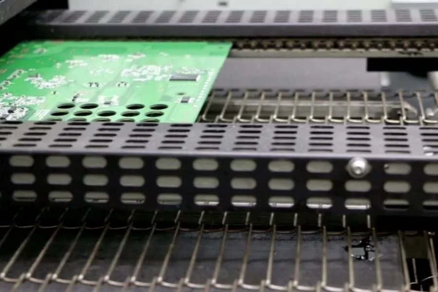
Step 7: Reflow Soldering
The assembled board passes through a controlled reflow profile.
The thermal profile must account for:
- Solder-paste alloy
- PCB material
- Component sensitivity
- Board thickness
- Thermal mass
Correct reflow control helps prevent:
- Tombstoning
- Bridging
- Insufficient solder
- Head-in-pillow defects
- Component damage
Step 8: Through-Hole Assembly
If the prototype includes THT components, the assembly may use:
- Manual insertion
- Automated insertion
- Wave soldering
- Selective soldering
Kingda supports both manual and automated through-hole assembly as well as selective soldering. (gopcba.com)
Step 9: Inspection
Prototype boards require careful inspection because defects found at this stage can prevent inaccurate engineering conclusions.
Typical inspection methods include:
AOI
Automated Optical Inspection (AOI) can detect:
- Missing components
- Misalignment
- Incorrect polarity
- Solder defects
X-Ray
X-Ray Inspection can inspect hidden solder joints, including BGA and other bottom-terminated packages.
FAI
First Article Inspection (FAI) verifies that the initial assembly conforms to defined specifications.
Kingda lists AOI, X-ray, FAI, ICT, and FCT among its prototype-testing capabilities. (gopcba.com)
Step 10: Functional Testing
Functional Testing verifies that the complete PCBA operates according to its intended specifications.
Testing may include:
- Power-up behavior
- Communication
- Sensor operation
- Processor functionality
- Analog signals
- Digital interfaces
- Firmware
- User interfaces
Kingda provides ICT and FCT, with FCT capable of incorporating IC programming and application-specific test procedures supplied by the customer. (gopcba.com)
Common Challenges in Prototype PCB Assembly
Component Shortages
Prototype orders may require small quantities of specialized components that are difficult to source.
An experienced manufacturer can help identify:
- Equivalent components
- Alternative manufacturers
- Compatible package options
However, any substitute should be technically validated before use.
Design Revisions
Prototype projects frequently undergo multiple revisions.
The manufacturer must maintain accurate revision control for:
- Gerber files
- BOM
- Pick-and-place files
- Assembly drawings
- Firmware
- Testing documents
Fine-Pitch Assembly
Advanced components can make prototype assembly more difficult.
Challenges may include:
- BGA soldering
- QFN bottom termination
- Fine-pitch components
- Tiny passive components
Signal Integrity
High-speed prototype boards may reveal issues involving:
- Crosstalk
- Impedance mismatch
- Reflections
- Timing
- Grounding
Physical prototype testing is therefore an important complement to simulation.
When Should You Use Prototype PCB Assembly?
Prototype PCB Assembly should normally be considered when:
Developing a New Product
The engineering team needs to validate the initial architecture.
Testing a New PCB Revision
A revised board should be physically tested before production release.
Developing High-Speed Electronics
High-speed boards often require physical validation of SI/PI behavior.
Developing Complex Electronics
Products containing BGA, QFN, HDI, RF, or high-density circuits benefit from prototype validation.
Preparing for Mass Production
A prototype can be used to validate assembly processes and testing procedures before volume manufacturing.
Conducting Compliance Testing
Prototype boards may be required for:
- EMC testing
- Thermal testing
- Mechanical testing
- Regulatory evaluation
Prototype PCB Assembly for Different Industries
Prototype PCBA is widely used across electronics sectors.
Automotive
Applications include:
- ADAS
- EV electronics
- BMS
- Vehicle controllers
Medical
Applications include:
- Diagnostic devices
- Monitoring equipment
- Portable medical electronics
Industrial Automation
Prototype boards are used for:
- PLCs
- Motor controllers
- Industrial gateways
- Robotics
AI and Computing
AI hardware requires advanced:
- High-speed PCBs
- High-density assembly
- Thermal management
- Power delivery
IoT
IoT products often require compact, low-power wireless electronics and rapid design iteration.
Aerospace and Defense
Prototype validation is particularly important for high-reliability electronics where design changes can be expensive once production begins.
Prototype-to-Production with Kingda
A major advantage of choosing an experienced manufacturer is the ability to continue from prototype assembly into low-volume and volume production.
Kingda positions its services around:
Rapid Prototyping → Low-Volume Production → Volume Production
Its published prototype services state that the company supports both quick-turn prototypes and subsequent production runs. (gopcba.com)
This creates a smoother transition because the same manufacturing partner can understand:
- The PCB design
- BOM
- Component sourcing
- Assembly requirements
- Testing requirements
- Previous prototype issues
Kingda’s Key Advantages for Prototype PCB Assembly
1. Rapid Prototype Production
Kingda lists normal prototype lead times of 2–3 days and an expedited option as fast as 12 hours, depending on project requirements and component readiness. (gopcba.com)
2. No Minimum Order Quantity
Kingda’s prototype service is published as supporting no MOQ, which is useful for early-stage engineering projects. (gopcba.com)
3. Advanced Component Capability
Kingda supports:
- 01005 components
- BGA
- QFN
- CSP
- LGA
- Fine-pitch components
Its prototype capability lists 0.25 mm minimum BGA pitch and 01005 minimum SMD component size. (gopcba.com)
4. Multiple Testing Methods
Kingda supports:
AOI + X-Ray + ICT + FCT + FAI
This provides multiple layers of quality verification during prototype development. (gopcba.com)
5. Engineering and DFM Support
Kingda provides engineering review before production and helps identify design issues through DFM analysis, including review of the BOM and Gerber files. (gopcba.com)
6. SMT, THT, and Mixed Assembly
Kingda can support:
- SMT
- Through-hole
- Mixed technology
- Selective soldering
- Manual assembly
This is important for prototypes containing a combination of modern SMT devices and larger mechanical or connector components. (gopcba.com)
7. One-Stop Manufacturing
Kingda integrates:
PCB Fabrication + Component Procurement + PCB Assembly + Testing + Finished Product Assembly
The company describes itself as a one-stop PCBA manufacturer supporting design and development, PCB manufacturing, component procurement, SMT, DIP, finished-product assembly, and testing. (gopcba.com)
8. Quality Management Certifications
Kingda reports:
- IATF 16949:2016
- ISO 13485:2016
- ISO 9001:2015
- ISO 14001:2015
- UL
The company also states that it is an IPC member. (gopcba.com)
FAQ About Prototype PCB Assembly
What is the typical prototype PCB assembly lead time?
The lead time depends on board complexity, components, quantity, and testing. Kingda currently publishes a normal prototype lead time of 2–3 days, with expedited prototype production as fast as 12 hours for qualifying projects. (gopcba.com)
Can prototype boards be used for mass production?
Yes, but prototype results should be reviewed before volume production. The design may require DFM optimization, component substitutions, panelization, or test-process adjustments before scaling.
Does prototype assembly support BGA and QFN?
Yes. Kingda lists support for BGA, QFN, CSP, LGA, and 01005 components within its assembly capabilities. (gopcba.com)
What files are required for prototype PCBA?
Typical documents include:
- Gerber files
- BOM
- Pick-and-place files
- Assembly drawings
- Schematics where necessary
- Testing requirements
Providing complete and consistent documentation can significantly reduce engineering delays.
Can the manufacturer handle design revisions?
Yes. Prototype manufacturing is inherently iterative. A capable manufacturer should maintain revision control and update the BOM, Gerber files, placement data, assembly instructions, and testing documentation accordingly.
Is functional testing available?
Yes. Kingda provides ICT and FCT, and its prototype service also lists IC programming and customized functional testing. (gopcba.com)
Conclusion
Prototype PCB Assembly is one of the most important stages in electronic product development. It transforms a digital PCB design into physical hardware that engineers can test, evaluate, modify, and ultimately qualify for production.
The key benefits include:
Early Error Detection + Faster Validation + Lower Development Risk + Faster Iteration + Better Manufacturing Readiness
For modern products containing BGA, QFN, 01005, HDI, RF, high-speed interfaces, flexible circuits, or mixed-technology components, prototype assembly should be treated as an engineering validation stage rather than simply a small production order.
Kingda provides rapid PCB prototyping, SMT/THT assembly, component sourcing, DFM review, AOI, X-ray, FAI, ICT, FCT, IC programming, and prototype-to-volume manufacturing, with published prototype lead times of 2–3 days and expedited options as fast as 12 hours for qualifying projects. (gopcba.com)
With IATF 16949, ISO 13485, ISO 9001, ISO 14001, and UL qualifications, Kingda can support prototype development for automotive, medical, industrial, AI, IoT, telecommunications, power electronics, and other demanding applications. (gopcba.com)