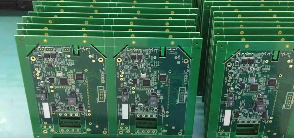
PCB Files: A Complete Guide to PCB Design, Gerber Files, and File Conversion
PCB Files are essential throughout the electronic product development and manufacturing process. From schematic design and PCB layout to fabrication and assembly, engineers must prepare accurate and complete design data to ensure that the final circuit board matches the intended electrical and mechanical requirements.
Different electronic design automation (EDA) tools use different file formats, while PCB manufacturers typically rely on production-ready files such as Gerber and NC drill files. Understanding the relationship between these formats can help engineers reduce manufacturing errors, improve communication with PCB manufacturers, and accelerate the transition from design to production.
For customers who need both fabrication and assembly, GOPCBA provides integrated PCB Manufacturing services covering a wide range of PCB technologies and materials.
What Are PCB Files?
In a typical PCB development project, several types of PCB Design Files may be created. When using Altium Designer, for example, a project may contain schematic documents, PCB layout documents, schematic libraries, and PCB footprint libraries.
Common Altium file types include:
.SchDoc— Schematic document.PcbDoc— PCB layout document.SchLib— Schematic library.PcbLib— PCB footprint library
The general PCB design workflow is:
Schematic Library → PCB Footprint Library → Schematic Design → PCB Layout → Component Placement → Routing → Copper Pour → Design Verification → Manufacturing Output
The schematic defines the electrical relationships between components, while the PCB layout determines the physical placement and routing of those components on the board.
After the design is completed, manufacturing data must be generated and verified before the PCB can enter production.
Why Are Gerber Files Used for PCB Manufacturing?
Gerber Files are one of the most widely used data formats for PCB fabrication. They provide the manufacturing information required to reproduce individual PCB layers.
A Gerber file typically represents a specific layer of a printed circuit board, such as:
- Top copper
- Bottom copper
- Inner copper layers
- Top solder mask
- Bottom solder mask
- Top silkscreen
- Bottom silkscreen
- Paste layers
- Board outline
NC drill data is normally supplied separately and contains information required to drill holes in the PCB.
Common Gerber formats include RS-274X and Gerber X2. Gerber X2 can provide additional layer and attribute information, making it useful for modern PCB manufacturing workflows.
When customers submit manufacturing data, a manufacturer can use the Gerber and drill files to generate the CAM data required for fabrication.
GOPCBA also supports PCB fabrication together with PCB assembly, allowing customers to use one manufacturing partner for the complete production process. Its manufacturing capabilities cover standard, multilayer, RF, rigid-flex, metal-backed, and other PCB technologies.
PCB Design Files vs. Gerber Files
A common question is why engineers should provide Gerber files instead of sending the original PCB design files directly to a manufacturer.
Original PCB design files are created in specific EDA software environments. Different software versions may interpret or process the same source data differently. In addition, manufacturers generally need to convert the source PCB design into production data before fabrication.
This conversion process can introduce potential risks if the output data is not carefully reviewed.
For example:
- Layer definitions may be incorrect.
- Unwanted design information may remain in the output.
- Board dimensions may be misinterpreted.
- Special pads may not be converted correctly.
- Drill information may be incomplete.
- Solder mask openings may not match the original design.
- Manufacturing notes may be missing.
For this reason, experienced PCB engineers normally generate the final Gerber Files themselves and review the output using CAM software before sending the files to a PCB manufacturer.
What Files Are Included in a Typical PCB Manufacturing Package?
A complete PCB manufacturing package usually contains multiple production files.
Copper Layer Files
Copper Gerber files define the conductive copper patterns on each layer of the PCB.
Depending on the board structure, the package may contain:
- Top copper
- Bottom copper
- Inner layer 1
- Inner layer 2
- Additional inner copper layers
Solder Mask Files
Solder mask files define the areas where solder mask should be applied or removed.
They are particularly important for defining solderable pads and openings around components.
Silkscreen Files
Silkscreen files contain reference designators, component markings, logos, polarity indicators, and other printed information.
Paste Files
For SMT production, solder paste layers define where solder paste should be deposited before component placement.
Board Outline
The board outline defines the physical dimensions and shape of the PCB. It is critical because the manufacturer uses this information for routing, milling, panelization, and other fabrication operations.
NC Drill Files
NC Drill Files contain the hole locations, hole sizes, quantities, and other drilling information required for PCB manufacturing.
They may define:
- Plated through holes
- Non-plated through holes
- Via holes
- Mounting holes
- Component holes
- Mechanical holes
A complete manufacturing package should ensure that the drill information matches the PCB layout and board outline.
How to Identify Correct Gerber Files
Correct identification of Gerber files is essential before manufacturing begins.
Gerber data normally contains graphical information combined with aperture definitions and coordinates.
D-Code and Aperture Information
Aperture definitions, traditionally associated with D-codes, determine the shape and dimensions used to create graphical features.
Without the correct aperture information, traces may not have the correct width and pads may appear only as outlines.
In some workflows, aperture information may be included directly in the Gerber file. In other cases, additional identification or manual configuration may be required.
Coordinate Information
Coordinate data determines the location of graphical features and drilling positions.
It is especially important for:
- Board dimensions
- Hole positions
- Component locations
- Pads
- Tracks
- Cutouts
If coordinate or format information is incorrect, the resulting PCB may not match the original design.
CAM Verification
Before production, manufacturers and engineers can use CAM software to verify:
- Layer sequence
- Board dimensions
- Copper patterns
- Drill locations
- Solder mask openings
- Silkscreen positioning
- Clearances
- Pad sizes
- Special features
For customers requiring engineering support, GOPCBA provides PCB design and manufacturing engineering services, including Gerber review and manufacturing-data verification.
What Are NC Drill Files?
NC Drill Files are used to control CNC drilling equipment during PCB manufacturing.
The file provides the drilling machine with information such as:
- Hole coordinates
- Hole diameters
- Tool numbers
- Plated or non-plated hole requirements
- Units
- Coordinate format
A typical NC drill file may begin with an M48 header, followed by tool definitions and drilling coordinates.
The file format can contain information about:
- Metric or imperial units
- Leading or trailing zero suppression
- Coordinate precision
- Tool diameter
- Drill locations
The coordinate format may be represented by values such as 3:3 or 4:3, depending on the specific manufacturing data and software configuration.
Correctly matching the NC drill data with the Gerber layers is essential for producing a PCB with accurate holes and vias.
Common PCB File Extensions
Different EDA and PCB design platforms use different file extensions.
Altium Designer and Protel
Common formats include:
.PCB.PcbDoc.SchDoc.SchLib.PcbLib
Altium Designer evolved from the Protel design environment and remains widely used for professional PCB design.
Cadence Allegro
Cadence PCB projects commonly use:
.BRD
PADS and Other EDA Tools
Depending on the software and export workflow, PCB-related data may use formats such as:
.ASC.CAM.TGZ
ODB++ is another important manufacturing-data format used by PCB production workflows.
Because file formats vary between design platforms, engineers should always confirm the exact production format required by the PCB manufacturer.
How to Open PCB Files
Opening PCB Files with Protel
Older PCB projects created with Protel can be opened using compatible Protel software versions.
However, compatibility may depend on the original software version and the specific PCB file format.
Opening PCB Files with Altium Designer
Altium Designer supports modern PCB design files and can work with many legacy Protel formats.
It is commonly used for:
- Schematic design
- PCB layout
- Library management
- Design-rule checking
- Gerber generation
- NC drill generation
Opening PCB Files with PADS
PADS is another professional PCB design platform that supports schematic and PCB layout development.
Engineers may use PADS to create production-ready PCB data and export the required manufacturing files.
For customers who need professional PCB layout and engineering assistance, GOPCBA provides PCB Design & Layout services covering layout evaluation, design verification, DFM inspection, and manufacturing-data output.
How to Convert Gerber Files Back to PCB Data
Gerber files are primarily manufacturing files rather than complete native PCB design files. Therefore, converting Gerber data back into an editable PCB project can be more difficult than generating Gerber files from an original design.
Nevertheless, CAM software can sometimes reconstruct PCB graphical information from Gerber and NC drill files.
Method 1: Convert Gerber to DXF
One approach is to import Gerber data into CAM software and export the graphical information as DXF.
A new PCB project can then be created and the DXF data imported.
However, this method may not reconstruct all original design information, especially:
- Component relationships
- Original net names
- Design rules
- Component libraries
- Schematic relationships
- Original layer properties
Therefore, DXF conversion should generally be considered a data-reconstruction method rather than a replacement for the original PCB source files.
Method 2: Import Gerber and NC Drill Data into CAM Software
Another method is to create a CAM project and import:
- Gerber files
- NC drill files
- Board outline
- Aperture information
- Optional IPC-D-356 netlist information
The CAM software can then analyze the imported layers and reconstruct the physical PCB structure.
If IPC-D-356 data is available, it may help restore network information and improve the accuracy of the reconstructed PCB data.
After checking all layers, drill information, and nets, the CAM project may be exported into a PCB format supported by the target EDA software.
How to Convert Gerber Files into PCB Data with Altium Designer
Altium Designer can also be used in certain workflows to reconstruct PCB graphical information from Gerber files.
A typical workflow includes:
Step 1: Create a CAM Document
Open Altium Designer and create a new CAM document.
Step 2: Import Gerber Files
Use the Gerber import function to load the required PCB layers.
Verify each layer carefully after import.
Step 3: Import NC Drill Data
Import the corresponding NC Drill Files and verify the hole locations and tool sizes.
Step 4: Extract the Netlist
If the required network information is available, extract the nets from the imported data.
Without appropriate network information, the reconstructed PCB may not contain the same logical net structure as the original design.
Step 5: Export to PCB
After verifying the CAM data and network information, export the CAM project into a PCB document.
The resulting PCB should then be compared against the original design whenever the original design data is available.
How to Transfer PCB Files to Gerber

The normal process for generating Gerber Files from a PCB design involves two major stages:
- Generate Gerber production files.
- Generate NC drill files.
Using Altium Designer as an example, the engineer can open the required .PcbDoc file and access the Gerber generation function.
During Gerber setup, engineers should carefully configure:
- Units
- Coordinate format
- Layer selection
- Aperture settings
- Film polarity
- Board outline
- Solder mask
- Silkscreen
- Paste layers
For NC drill generation, engineers should verify whether the project uses metric or imperial units and select the appropriate coordinate precision.
After generation, the final files should be reviewed in CAM software.
DXF to Gerber Conversion
DXF files are commonly used for mechanical drawings and board outlines.
When a DXF file needs to be converted into manufacturing data, CAM software such as CAM350 can be used to import the DXF and generate appropriate PCB production layers.
The general workflow is:
DXF → CAM Import → Layer Definition → Manufacturing Data Verification → Gerber Export
ODB++ and other intelligent manufacturing-data formats may also be supported by modern CAM systems, depending on the software and production environment.
PCB File Conversion Risks
File conversion between different EDA and CAM platforms can introduce potential manufacturing risks.
Special attention should be paid to:
- Special-shaped pads
- Board outlines
- Slots and cutouts
- Drill sizes
- Layer polarity
- Copper clearances
- Solder mask openings
- Net information
- Component footprints
- Text and silkscreen
- Impedance requirements
The converted files should always be compared with the original PCB design whenever possible.
This is particularly important for complex boards such as HDI, high-frequency, rigid-flex, and controlled-impedance PCBs.
For projects requiring both fabrication and assembly, it is also important to verify that the manufacturing files are consistent with the BOM, pick-and-place data, and assembly requirements. GOPCBA provides integrated PCB Assembly Services from prototype development through production, including SMT, THT, mixed-technology assembly, component sourcing, testing, and box-build integration.
PCB Files for Prototype and Production
The file requirements for PCB prototypes and production are generally similar, but production projects often require more detailed engineering verification.
For prototype projects, engineers should at minimum provide:
- Gerber files
- NC drill files
- Board outline
- BOM
- Pick-and-place data when assembly is required
- Assembly drawings when necessary
For more complex projects, additional information may include:
- Stack-up requirements
- Controlled impedance specifications
- IPC-D-356 data
- Mechanical drawings
- Special fabrication notes
- Material requirements
- Surface-finish requirements
For rapid development, Prototype PCB Assembly can help engineers validate the design before committing to larger production quantities. GOPCBA states that its prototype service supports rapid PCB fabrication, component procurement, assembly, testing, and transition toward production.
Best Practices for Preparing PCB Manufacturing Files
To minimize manufacturing problems, engineers should follow several basic practices.
1. Generate Production Files from the Final PCB Revision
Always generate manufacturing data from the latest approved PCB design.
2. Check All Layers
Verify every copper, solder mask, silkscreen, paste, and mechanical layer before release.
3. Verify the Board Outline
The board outline must accurately represent the finished PCB dimensions.
4. Check Drill Data
Confirm hole sizes, locations, quantities, and plated/non-plated requirements.
5. Review the Gerber Data in CAM Software
Do not assume that exported files are automatically correct. Open and inspect them before production.
6. Match PCB Files with BOM and Assembly Data
For PCBA projects, the PCB design should be consistent with the BOM and component placement data.
7. Clearly Identify the Revision
Use clear revision numbers or version identifiers to prevent outdated files from entering production.
8. Provide Complete Manufacturing Documentation
Clear documentation reduces communication problems and helps the manufacturer identify special requirements before production starts.
GOPCBA’s engineering workflow includes DFM review, BOM verification, Gerber review, pick-and-place verification, component availability analysis, and manufacturing-document verification.
PCB Files and the Manufacturing Process
A complete PCB manufacturing workflow can be summarized as:
PCB Design → Design Verification → Gerber Generation → NC Drill Generation → CAM Review → PCB Fabrication → Component Procurement → PCB Assembly → Testing → Final Delivery
For customers looking for an integrated production solution, GOPCBA supports PCB manufacturing, component sourcing, SMT/THT assembly, testing, and final product integration through its one-stop electronics manufacturing model.
Conclusion
Understanding PCB Files, Gerber Files, PCB Design Files, NC Drill Files, and PCB File Conversion is essential for reliable PCB manufacturing.
Native PCB design files contain valuable design information, but Gerber and NC drill files are commonly used to communicate production requirements to PCB manufacturers. Before manufacturing, engineers should carefully verify the exported data, layer structure, board dimensions, drill information, solder mask, silkscreen, and other critical production details.
When converting files between different EDA and CAM platforms, additional verification is necessary because some design information may not transfer completely.
For projects requiring PCB fabrication, assembly, component sourcing, testing, or prototype-to-production support, GOPCBA’s PCB Manufacturing Services provide an integrated manufacturing path from PCB data preparation through finished electronic products.
If you are ready to manufacture your next PCB project, you can Request a PCB Quote and submit your Gerber, BOM, drawing, PDF, or other production files for engineering review.