Metal Stiffener Rigid-Flex PCB: Complete Design and Manufacturing Guide
A Metal Stiffener Rigid-Flex PCB combines the flexibility of a flexible circuit with the mechanical stability required in selected areas of a rigid-flex circuit. While the rigid-flex structure itself provides both rigid and flexible sections, some applications require additional reinforcement around connectors, component mounting areas, through-hole components, or mechanically stressed regions.
A properly designed Metal PCB Stiffener can increase local rigidity without eliminating the flexibility of the intended bend area. Depending on the application, stainless steel, aluminum, copper, brass, FR-4, or polyimide can be selected as reinforcement materials.
For electronics manufacturers looking for integrated PCB fabrication and assembly, GOPCBA provides one-stop PCB and PCBA manufacturing services covering PCB fabrication, component sourcing, SMT, DIP, testing, and finished-product assembly. Learn more about GOPCBA PCB Manufacturing and PCBA Solutions.
What Is a PCB Stiffener?
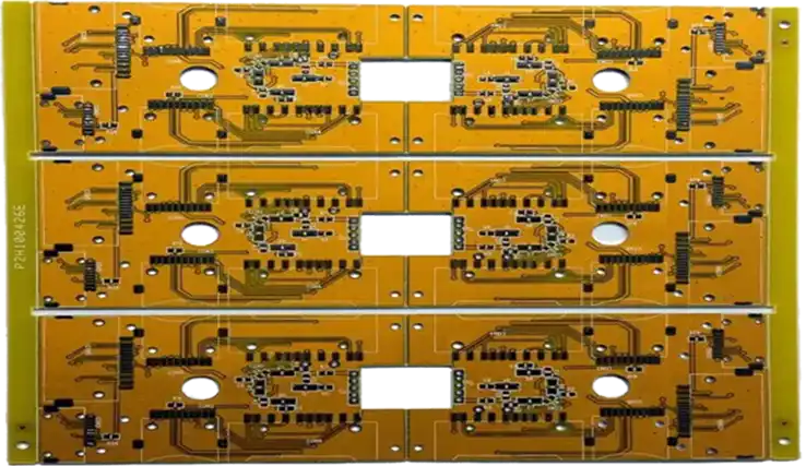
A PCB stiffener is an additional material attached to a selected section of a flexible or rigid-flex circuit to increase mechanical strength and dimensional stability.
Unlike a conventional rigid PCB, a flexible circuit is designed to bend and conform to limited installation spaces. However, some areas cannot remain highly flexible because components, connectors, or mechanical interfaces require a stable mounting surface.
The stiffener provides localized reinforcement while allowing the rest of the flexible circuit to retain its designed flexibility.
A stiffener can help:
- Support components installed on flexible sections
- Reinforce connector areas
- Improve mechanical stability around mounting holes
- Maintain flatness in selected PCB areas
- Improve handling of thin flexible circuits
- Support ZIF connector requirements
- Reduce mechanical stress at rigid-to-flex transitions
- Increase the effective bend radius around reinforced regions
- Improve alignment and retention of PCB arrays
The reinforcement material and thickness should always be selected according to the mechanical, thermal, electrical, and assembly requirements of the final application.
Common PCB Stiffener Materials
Common stiffener materials include:
- Polyimide
- FR-4
- Stainless steel
- Aluminum
- Copper
- Brass
Polyimide and FR-4 are widely used when electrical insulation and moderate reinforcement are required. Metal stiffeners become attractive when higher mechanical strength, thinner reinforcement, or thermal conduction is important.
For projects that require both PCB fabrication and assembly, GOPCBA PCB Assembly Services can integrate PCB manufacturing with SMT, through-hole, mixed-technology, and other assembly requirements.
Why Use a Metal PCB Stiffener in Rigid-Flex Circuits?
A Metal PCB Stiffener is particularly useful when the flexible section must provide mechanical support without becoming excessively thick.
Flexible circuits are often selected because they can fit into compact mechanical structures. However, this flexibility can become a disadvantage around connectors, component mounting areas, and interfaces that experience repeated mechanical loads.
A metal stiffener addresses this problem by reinforcing only the required section.
The main benefits include:
- Higher local mechanical strength
- Improved connector support
- Better dimensional stability
- Improved component mounting support
- Reduced deformation during assembly
- Better resistance to vibration and handling
- Potentially improved thermal conduction
- Thin reinforcement for space-constrained designs
The stiffener should not extend into areas that must remain flexible. Its geometry, edge location, thickness, and bonding method all affect the bending behavior of the finished rigid-flex PCB.
Metal Stiffeners for Rigid-Flex PCB Applications
Metal reinforcement is commonly considered when a conventional polyimide or FR-4 stiffener cannot provide the required combination of strength, thickness, thermal performance, or mechanical durability.
Stainless Steel Stiffener
A Stainless Steel Stiffener is a strong and durable option for rigid-flex circuits that require high mechanical rigidity in a limited area.
Stainless steel offers good dimensional stability and resistance to corrosion. Thin stainless-steel sheets can be cut into custom profiles using precision mechanical or laser processing, making them suitable for specialized PCB geometries.
Stainless steel is particularly useful in applications exposed to:
- Mechanical vibration
- Repeated handling
- Temperature variation
- High humidity
- Mechanical impact
- Limited installation space
Because stainless steel can provide substantial rigidity at relatively small thicknesses, it can be useful when a reinforced section must remain thin.
Advantages of Stainless Steel Stiffeners
A stainless-steel reinforcement can provide:
- High mechanical strength
- Good corrosion resistance
- Excellent dimensional stability
- Good temperature resistance
- Customizable shapes and sizes
- Thin reinforcement for compact assemblies
- Long-term mechanical durability
Limitations of Stainless Steel Stiffeners
There are also several considerations:
- Higher material cost than many non-metal stiffeners
- Higher density than aluminum
- More demanding processing requirements
- Requires an appropriate bonding system
- Can add mechanical weight to the assembly
Therefore, stainless steel is best selected when its mechanical performance justifies the additional material and processing cost.
Aluminum Stiffener
An Aluminum Stiffener is another widely considered metal reinforcement option for flexible and rigid-flex circuits.
Aluminum combines relatively low density with good thermal conductivity and machinability. This makes it attractive for applications where reinforcement and heat dissipation are both important.
Compared with stainless steel, aluminum is generally lighter and easier to machine into different shapes. It can therefore be useful for electronic products where weight reduction is an important design objective.
Advantages of Aluminum Stiffeners
An aluminum reinforcement can provide:
- Low weight
- Good thermal conductivity
- Good machinability
- High strength-to-weight efficiency
- Customizable geometry
- Effective support for thin PCB sections
- Potential thermal-management benefits
In applications where components generate significant heat, an aluminum reinforcement may also contribute to heat spreading, depending on the mechanical and electrical design.
Limitations of Aluminum Stiffeners
Designers should also consider:
- Thermal expansion differences between materials
- Potential deformation under certain thermal conditions
- Surface treatment requirements
- Bonding and assembly considerations
- Corrosion protection when exposed to unsuitable environments
Material selection should therefore consider the complete thermal and mechanical stack-up rather than the stiffener material alone.
Other Metal Reinforcement Materials
Copper and brass can also be used in specialized PCB applications.
Copper has excellent electrical and thermal conductivity and may be used where reinforcement is combined with current-carrying requirements. Copper is also useful in busbar structures where substantially higher current capacity is required than ordinary PCB traces can provide.
Brass, an alloy primarily composed of copper and zinc, can also be used for specialized mechanical or electrical structures.
However, a busbar should not automatically be considered equivalent to a conventional PCB stiffener. A busbar is primarily intended to carry significant electrical current, while a stiffener is primarily intended to improve mechanical rigidity.
The appropriate material therefore depends on whether the design objective is mechanical reinforcement, thermal management, current conduction, or a combination of these functions.
Design Requirements for Metal Stiffeners
Before adding a metal reinforcement to a rigid-flex design, several factors should be evaluated.
Thickness
The stiffener thickness must provide sufficient rigidity without creating an unwanted step or interfering with nearby mechanical components.
Common thin-metal reinforcement thicknesses may include:
Stainless steel: approximately 0.15 mm and 0.20 mm
Aluminum: approximately 0.15 mm, 0.20 mm, 0.25 mm, 0.30 mm, 0.35 mm, 0.40 mm, 0.45 mm, 0.50 mm and, for selected mechanical structures, thicker options.
Actual available thicknesses should be confirmed during engineering review because material availability and manufacturing capability vary by supplier.
Edge Geometry
The edges of the metal reinforcement should be properly designed and finished.
Sharp corners can create localized stress concentrations and may damage adjacent flexible materials. Rounded corners and appropriate edge clearances can help reduce mechanical stress.
Flex-to-Rigid Transition
One of the most important considerations is the transition between the flexible area and the reinforced area.
The stiffener should not extend into the dynamic bending zone unless the design specifically requires it. Adequate clearance around the stiffener edge allows the flexible circuit to bend naturally.
Poorly positioned reinforcement can create a sharp mechanical transition and increase stress concentration in the flex circuit.
How to Integrate a Metal Stiffener into PCB Design
1. Define the Reinforced Area
First identify the areas that require additional rigidity.
Typical locations include:
- Connector interfaces
- ZIF connector areas
- Through-hole component regions
- Mounting points
- Component support areas
- Mechanical fastening locations
- Flexible-to-rigid transition areas
Only the required areas should be reinforced so that unnecessary weight, thickness, and cost are avoided.
2. Select the Appropriate Material
Choose between stainless steel, aluminum, FR-4, polyimide, copper, or other materials according to:
- Required rigidity
- Available space
- Weight restrictions
- Thermal requirements
- Electrical requirements
- Environmental conditions
- Cost
- Assembly method
For high-reliability projects, the material selection should be reviewed together with the PCB stack-up and manufacturing process.
3. Define the Attachment Method
Metal stiffeners generally require an appropriate bonding system.
Common options include:
- Pressure-sensitive adhesive (PSA)
- Thermally activated adhesive
- Double-sided adhesive film
- Silicone-based adhesive
- Lamination using heat and pressure
The selected adhesive must provide sufficient adhesion and withstand the expected temperature, humidity, vibration, and mechanical conditions.
4. Define the Stiffener Profile
The reinforcement profile should match the PCB geometry accurately.
Laser cutting is commonly used when precise custom shapes are required. The design should account for dimensional tolerances, edge clearance, adhesive thickness, and assembly alignment.
5. Consider Component and Connector Assembly
When components or connectors are mounted near the reinforced region, the stiffener must not interfere with:
- Component placement
- Soldering
- Connector insertion
- Through-hole leads
- Inspection
- Testing
- Mechanical assembly
A properly designed reinforcement can make component installation easier by creating a stable mounting area.
Best Practices for Adding Metal Stiffeners
Several practical guidelines can improve the reliability of a Rigid-Flex PCB with metal reinforcement.
Maintain Adequate Overlap
The stiffener should provide sufficient overlap with the intended reinforced area and cover layer according to the PCB manufacturer’s process recommendations. In some designs, an overlap of approximately 0.762 mm or more may be used as a reference, but the final value should be confirmed during engineering review.
Keep Reinforcement Away from Dynamic Bends
Do not place rigid reinforcement inside a section intended for repeated dynamic bending unless the mechanical design specifically requires it.
The flexible section needs enough length and clearance to achieve its specified bend radius without creating excessive stress.
Consider Adhesive Thickness
Adhesive is part of the mechanical stack-up. Its thickness affects the final PCB thickness, connector fit, step height, and mechanical transition.
Match the Reinforcement to the Assembly Process
For boards containing through-hole components, stiffener placement should allow component leads to pass through the appropriate holes without interference.
The reinforcement should also be compatible with SMT and other assembly processes.
Review the Complete Stack-Up
The final stack-up should account for:
- Copper thickness
- Flexible dielectric layers
- Coverlay
- Stiffener
- Adhesive
- Surface finish
- Component height
- Connector dimensions
- Mechanical enclosure requirements
A complete stack-up review helps prevent dimensional problems during final assembly.
Typical Metal Stiffener Thicknes
The thickness of the reinforcement depends on the required mechanical strength and available installation space.
Typical examples include:
Stainless Steel
- 0.15 mm
- 0.20 mm
Aluminum
- 0.15 mm
- 0.20 mm
- 0.25 mm
- 0.30 mm
- 0.35 mm
- 0.40 mm
- 0.45 mm
- 0.50 mm
- 1.50 mm for selected rigid mechanical applications
These values should be treated as common reference options rather than universal manufacturing limits. The final thickness should be selected according to the PCB design, connector requirements, bending conditions, and manufacturing process.
Metal Stiffener Rigid-Flex PCB Manufacturing Considerations
Manufacturing a Metal Stiffener Rigid-Flex PCB requires coordination between PCB fabrication, reinforcement processing, bonding, assembly, and inspection.
Important manufacturing checkpoints include:
- Confirm the rigid-flex stack-up.
- Confirm flex and rigid section dimensions.
- Define the stiffener material and thickness.
- Verify adhesive specifications.
- Confirm stiffener profile and tolerances.
- Check connector and component clearances.
- Verify bend zones and bend radius.
- Inspect bonding and alignment.
- Perform electrical and mechanical testing.
- Complete final inspection before shipment.
GOPCBA’s manufacturing model integrates PCB fabrication, component procurement, SMT/DIP assembly, testing, and other electronic manufacturing processes, helping customers manage multiple production steps through one manufacturing partner. More information is available on the GOPCBA About Us page.
PCB and PCBA Capability for Complex Applications
Rigid-flex circuits with metal reinforcement are often used in applications where space, mechanical stability, weight, and electrical performance must be balanced.
Potential applications include:
- Medical electronics
- Automotive electronics
- Industrial control
- Communication equipment
- Consumer electronics
- Smart-home products
- IoT equipment
- Aerospace electronics
- Security equipment
- Portable electronic devices
For projects that require assembled boards rather than bare PCBs, GOPCBA supports prototype, low-volume, high-volume, turnkey, SMT, through-hole, mixed-technology, and flex PCB assembly services. Customers can review the available PCB Assembly Solutions from GOPCBA when selecting a suitable production route.
Why Choose GOPCBA for Rigid-Flex PCB and PCBA Manufacturing?
A reliable manufacturing partner should be able to evaluate the complete project rather than treating the stiffener as an isolated component.
GOPCBA provides integrated PCB manufacturing and assembly capabilities, including PCB design support, PCB fabrication, component procurement, SMT assembly, DIP assembly, PCBA testing, and finished-product integration. Its official company information describes a one-stop manufacturing model designed to support projects from PCB production through assembly and testing.
Quality management is also an important part of the manufacturing process. GOPCBA describes controls covering PCB design review, DFM checking, new product introduction, PCBA manufacturing, supply-chain management, testing, and personnel training.
For customers developing complex rigid-flex products, working with an integrated manufacturer can simplify communication between PCB engineering, material selection, assembly engineering, and quality control.
You can learn more about the company’s capabilities and manufacturing approach through GOPCBA’s company information.
Conclusion
A metal stiffener can significantly improve the mechanical performance of a flexible or rigid-flex circuit when reinforcement is required around connectors, components, mounting points, or other mechanically sensitive areas.
Stainless steel provides high rigidity, durability, and dimensional stability, making it suitable for demanding mechanical environments. Aluminum provides a useful combination of low weight, machinability, and thermal conductivity, making it attractive when weight and heat management are important.
The key to a reliable reinforced rigid-flex design is not simply selecting a stronger metal. The stiffener thickness, profile, adhesive, placement, bend-zone clearance, PCB stack-up, connector interface, and assembly process must all work together.
For complex PCB projects, early communication between the designer and manufacturer can help identify mechanical and manufacturing risks before production begins. GOPCBA offers integrated PCB fabrication and PCBA manufacturing services to support projects from prototype development through production and testing.
For a complete manufacturing solution, visit GOPCBA and discuss your PCB or PCBA requirements with its engineering team.