High-Frequency PCB Manufacturing for Automotive Radar: Materials, Processes & Applications
With the rapid development of Advanced Driver Assistance Systems (ADAS) and autonomous driving technology, automotive radar has become one of the most essential sensing technologies in modern intelligent vehicles. Compared with cameras, radar continues to work reliably in rain, snow, fog, and at night, which is why it is widely used in adaptive cruise control, blind spot monitoring, automatic emergency braking, and other safety systems.
The key hardware that keeps automotive radar running stably is the high-frequency PCB. Because automotive radar typically operates in the 24 GHz, 77 GHz, and even 79 GHz millimeter-wave bands, its requirements for material performance, manufacturing precision, and reliability are far higher than those of ordinary circuit boards.
This article takes an in-depth look at material selection, design essentials, manufacturing processes, cost structure, and future trends for high-frequency PCB manufacturing, offering a practical reference for automotive electronics engineers, procurement teams, and project developers.
What Is an Automotive Radar High-Frequency PCB?
An automotive radar high-frequency PCB is a circuit board designed for RF and millimeter-wave signal transmission. It carries the radar transceiver modules, antenna arrays, power management circuits, and signal processing units.
Compared with standard FR4 boards, a high-frequency PCB provides:
- Lower dielectric loss (Df)
- More stable dielectric constant (Dk)
- Superior impedance control
- Higher signal integrity
- Stronger environmental adaptability
These characteristics allow the radar system to achieve accurate ranging and target recognition at high frequencies.
Main Applications
Automotive radar PCBs are widely used in:
- Adaptive Cruise Control (ACC)
- Blind Spot Detection (BSD)
- Forward Collision Warning (FCW)
- Automatic Emergency Braking (AEB)
- Lane Change Assist (LCA)
- Automatic parking systems
- Autonomous driving perception platforms
With the rollout of L2+, L3, and even L4 autonomous driving, a single intelligent vehicle often carries multiple radar modules, so demand for automotive radar PCBs is growing rapidly.

Why Do Automotive Radars Need High-Frequency PCB Technology?
Controlling High-Frequency Signal Transmission Loss
Automotive radar operates at frequencies far above ordinary electronic products. For example, 24 GHz, 77 GHz, and 79 GHz bands are common in today’s systems.
At these frequencies, standard FR4 material causes significant signal attenuation and phase error, which directly affects detection accuracy. Low-loss high-frequency materials are therefore essential to ensure:
- Lower insertion loss
- More stable impedance
- Higher signal quality
- Longer detection range
Extreme Precision Requirements of Millimeter-Wave Radar PCBs
In the 77 GHz and above bands:
- Line width errors can degrade antenna performance
- Lamination misregistration can cause impedance loss of control
- Copper foil roughness increases transmission loss
For this reason, the manufacturing process must deliver far tighter process control than ordinary PCB production.
Automotive-Grade Reliability Requirements
Automotive electronics must survive harsh conditions over a long service life:
- Operating temperature from -40°C to 125°C
- High humidity
- Continuous vibration
- Salt spray corrosion
- Chemical exposure
Automotive radar PCBs must pass strict reliability testing before they can satisfy OEM requirements.
Common Materials for Automotive Radar PCBs
Material selection is one of the most important factors in radar performance.
Rogers High-Frequency Laminates
Rogers high-frequency laminates are among the most widely used materials in automotive millimeter-wave radar PCBs.
Rogers RO4350B — Features: Dk≈3.48, low loss, excellent processability, and good cost-performance. It suits 24 GHz radar, 77 GHz radar, and ADAS control systems.
Rogers RO3003 — Features: Dk≈3.0, ultra-low loss, and excellent high-frequency performance. It suits 77 GHz radar, 79 GHz imaging radar, and autonomous driving perception modules.
Rogers RO4835T — Features: designed specifically for automotive electronics, strong oxidation resistance, and excellent long-term stability. It is ideal for harsh automotive environments.
PTFE Materials
PTFE offers extremely low dielectric loss. Its advantages include the best high-frequency performance, the lowest signal attenuation, and suitability for millimeter-wave applications. Its drawbacks are difficult processing, high manufacturing cost, and demanding yield control, so it is usually reserved for high-end autonomous driving radar projects.
Hybrid Laminates
To control cost, many automotive radar designs combine high-frequency layers (Rogers) with digital layers (FR4). This hybrid stackup balances performance and cost and has become an important direction for automotive radar PCBs.
Key Design Points for Automotive Radar High-Frequency PCBs
Impedance-Controlled Design
High-frequency signals must maintain strict impedance consistency. Common requirements are single-ended 50Ω and differential 100Ω traces. Impedance deviation can cause signal reflection, detection errors, and reduced sensitivity, so precise simulation and calculation are essential during the PCB design stage.
Integrated Antenna Design
Modern automotive radars typically adopt PCB antennas, including microstrip antennas, patch antennas, and phased array antennas. A well-planned antenna layout improves detection range, angular resolution, and target recognition.
Stackup Optimization
Common automotive radar PCB structures include 4-layer high-frequency PCBs, 6-layer hybrid PCBs, and 8-layer HDI millimeter-wave PCBs. Key design considerations are ground plane continuity, signal isolation, return path optimization, and EMI suppression.
Thermal Management
Long-term operation generates heat. Common solutions include thermal vias, thick copper, metal-core substrates, and heat sinks. Good thermal design improves system stability and service life.
Manufacturing Processes for Automotive Radar High-Frequency PCBs
Material Pre-Treatment
Rogers and PTFE laminates are sensitive to humidity. During production, manufacturers must apply constant temperature and humidity control, vacuum packaging storage, and baking to remove moisture.
Precision Circuit Patterning
77 GHz radar circuits are extremely small. The process requires high-precision exposure, fine etching, and strict line tolerance control to guarantee high-frequency signal performance.
Laser Drilling and HDI Technology
Modern automotive radars rely heavily on laser micro-vias, blind vias, buried vias, and via-in-pad structures. These technologies shorten signal paths and improve RF performance.
Multilayer Lamination
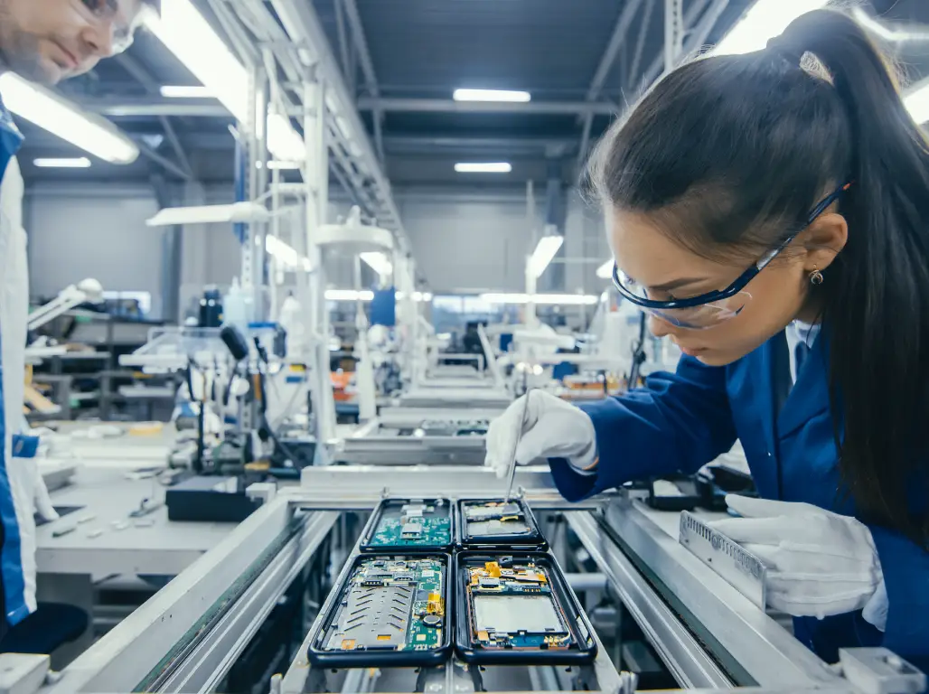
Lamination demands precise layer-to-layer registration, stable pressure control, and strict dielectric thickness management. Any deviation directly affects impedance consistency.
Surface Finishes
Common surface finishes for automotive radar PCBs include:
- ENIG (electroless nickel immersion gold): high flatness and strong oxidation resistance
- ENEPIG: high reliability and support for gold wire bonding
- Immersion silver: excellent RF performance and low high-frequency loss
Testing and Inspection
Automotive-grade radar PCBs undergo AOI optical inspection, X-ray inspection, flying probe testing, impedance testing, and RF performance testing to ensure compliance with automotive industry standards.
Cost Analysis of Automotive Radar PCBs
The main factors affecting the price of automotive radar PCBs include material cost, layer count and structural complexity, and HDI process requirements.
As layer count increases, lamination cycles grow, registration becomes more difficult, and yield drops, so manufacturing cost rises accordingly. Laser drilling, blind and buried vias, and via-in-pad technology also add significantly to processing cost.
As a general reference, unit cost falls sharply with scale: volume production typically reduces unit cost by 30–60% compared with prototypes.
Why Choose gopcb for Automotive Radar PCBs?
As a professional high-frequency PCB and automotive electronics PCB manufacturer, gopcb has rich experience in the automotive radar PCB field.
High-Frequency PCB Manufacturing Capabilities
gopcb supports Rogers PCB manufacturing, PTFE PCB processing, hybrid high-frequency PCBs, HDI radar PCBs, and impedance-controlled PCBs.
Automotive-Grade Quality System
Our production process strictly follows IPC standards, automotive electronics quality management requirements, and full traceability to ensure stable and reliable products.
Customized Automotive Radar Solutions
We support 24 GHz automotive radar PCBs, 77 GHz millimeter-wave radar PCBs, 79 GHz imaging radar PCBs, and ADAS system control boards to meet different project requirements.
Rapid Prototyping and Volume Production
gopcb provides fast PCB prototyping, small-batch trial production, large-scale mass production, and global logistics to help customers shorten time to market.
Future Trends in Automotive Radar PCBs
The Rise of 4D Imaging Radar
Future automotive radar will offer higher resolution, longer detection range, and more accurate target recognition, pushing PCBs toward higher layer counts and more complex structures.
Adoption of 79 GHz Radar
79 GHz technology provides wider bandwidth, higher accuracy, and stronger anti-interference capability, making it an important direction for intelligent driving.
New Low-Loss Materials
Future high-frequency materials will keep improving toward lower loss, higher thermal conductivity, and greater stability.
Autonomous Driving Drives Demand Growth
As autonomous driving levels rise, vehicles will integrate radar, cameras, LiDAR, and ultrasonic sensors, sustaining steady growth in the automotive radar PCB market.
Conclusion
The development of automotive radar systems is pushing high-frequency PCB manufacturing technology to the next level. From Rogers material selection and millimeter-wave antenna design to HDI processes and automotive-grade reliability testing, every step directly affects the detection performance and safety of the radar system.
For companies developing ADAS, 77 GHz millimeter-wave radar, and autonomous driving perception systems, choosing a partner with proven high-frequency PCB manufacturing experience is critical. With mature high-frequency board capabilities, a strict quality control system, and fast delivery, gopcb delivers high-performance, high-reliability automotive radar PCB solutions to customers around the world.