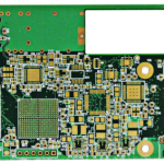
IPC Class 3 PCB: Design Rules, Requirements, Standards, and Manufacturing Guide
Modern electronic devices are becoming smaller, faster, and more sophisticated, with increasing numbers of components integrated into compact PCB assemblies. As a result, the quality, precision, and reliability of the printed circuit board (PCB) have a direct impact on the performance and service life of the final product.
To establish consistent quality requirements across the electronics industry, the IPC has developed a comprehensive family of standards covering PCB design, materials, fabrication, assembly, inspection, and acceptance criteria.
IPC divides electronic products into three classification levels based on their intended use and reliability requirements. Among them, IPC Class 3 applies to products where continued performance and high reliability are critical.
Class 3 requirements are commonly associated with applications such as aerospace, defense, medical equipment, automotive safety systems, industrial control, and other high-reliability electronics.
This guide explains what IPC Class 3 PCB means, the applicable standards, major design considerations, manufacturing requirements, inspection practices, advantages, challenges, and best practices for producing high-reliability circuit boards.
What Is IPC Class 3?
IPC Class 3 is a product classification for electronic assemblies that require continued high performance and where equipment downtime or failure can have serious consequences.
Unlike Class 1 products, where basic functionality is the primary consideration, and Class 2 products, where extended performance and reliability are important, Class 3 products are intended for applications where consistent performance is critical.
Typical Class 3 applications include:
- Aerospace and aviation electronics
- Defense and military electronics
- Medical and life-support equipment
- Automotive safety systems
- Industrial control systems
- High-reliability telecommunications
- Critical infrastructure
- High-performance computing systems
It is important to understand that IPC Class 3 PCB is not defined by a single specification. Requirements are determined by the applicable IPC standards, product type, customer requirements, materials, manufacturing processes, and acceptance criteria.
For example, IPC-6012 addresses qualification and performance specifications for rigid printed boards, while IPC-6013 covers flexible printed boards. Other standards, including IPC-2221 and IPC-A-600, address PCB design and acceptability requirements.
Therefore, manufacturers should identify the complete set of applicable IPC documents rather than relying on a single standard.
IPC PCB Classification System
The IPC classification system generally divides electronic products into three classes.
Class 1: General Electronic Products
Class 1 products are intended for applications where the major requirement is the function of the completed assembly.
Examples may include:
- Consumer electronics
- Toys
- Basic household electronics
- Low-cost electronic devices
Minor cosmetic imperfections may be acceptable when they do not affect the intended function.
Class 2: Dedicated Service Electronic Products
Class 2 applies to products that require continued performance and extended service life.
Typical applications include:
- Telecommunications equipment
- Industrial control systems
- Office equipment
- Commercial electronics
- Certain automotive and consumer products
These products require higher reliability than Class 1 products but generally do not demand the highest level of defect prevention associated with critical applications.
Class 3: High-Reliability Electronic Products
IPC Class 3 PCB applies to electronic products where continued performance is essential.
The consequences of failure can be significant, making reliability and manufacturing consistency especially important.
Typical applications include:
- Aerospace systems
- Defense electronics
- Medical equipment
- Automotive safety systems
- Critical industrial systems
- High-reliability communications equipment
The key principle of Class 3 is not simply that every dimension is smaller or every material is thicker. Instead, the class reflects the required level of product reliability and acceptance criteria for the intended application.
Key IPC Class 3 PCB Requirements
Compared with lower-reliability applications, Class 3 products generally require tighter control over materials, fabrication, assembly, inspection, and process consistency.
The exact requirements depend on the applicable IPC standard and product specification.
1. Plated Through-Hole Reliability
Plated through-holes and vias provide electrical connections between PCB layers.
For high-reliability applications, the plated copper structure must withstand thermal cycling, mechanical stress, and repeated manufacturing and operating conditions.
Important considerations include:
- Plating thickness
- Hole-wall integrity
- Copper adhesion
- Crack resistance
- Thermal reliability
- Aspect ratio
- Drill quality
- Plating uniformity
The exact minimum requirements should be determined from the applicable IPC specification and customer drawing rather than applying one universal copper-thickness value to every PCB.
2. Annular Ring Requirements
The annular ring is the copper area surrounding a drilled hole on a PCB pad.
Adequate annular-ring geometry is essential for maintaining reliable electrical and mechanical connections.
Problems such as excessive drill wander, registration errors, or insufficient pad dimensions can result in breakout.
For Class 3 products, manufacturing must maintain the required registration and annular-ring acceptance criteria defined by the applicable IPC standard.
Advanced PCB manufacturers may use automated optical inspection, X-ray inspection, cross-section analysis, and statistical process control to monitor these characteristics.
3. Trace Width and Conductor Spacing
Trace width and conductor spacing directly affect PCB electrical performance, current-carrying capacity, manufacturability, and insulation reliability.
However, there is no single universal trace width or spacing value that applies to every IPC Class 3 PCB.
The appropriate dimensions depend on:
- Copper thickness
- Internal or external layer
- Required current
- Temperature rise
- Operating voltage
- PCB material
- Manufacturing capability
- Impedance requirements
- Environmental conditions
For high-current circuits, wider copper traces or copper pours may be required.
For high-voltage circuits, sufficient creepage and clearance must be maintained.
For high-speed circuits, trace geometry must also be designed according to the required controlled impedance.
Therefore, PCB designers should use the applicable IPC design standards together with the actual electrical and manufacturing requirements.
4. Solder Joint Quality
Solder joints provide both mechanical attachment and electrical connection between components and the PCB.
For high-reliability assemblies, solder joints must withstand:
- Thermal cycling
- Mechanical vibration
- Shock
- Humidity
- Electrical stress
- Long-term operation
Inspection criteria may cover:
- Solder coverage
- Wetting
- Fillet formation
- Voids
- Cracks
- Component alignment
- Lead attachment
- Through-hole soldering
The acceptance criteria depend on the component package, assembly technology, and applicable IPC assembly standard.
For example, through-hole soldering and SMT soldering have different acceptance criteria, so they should not be evaluated using one generalized solder-fill rule.
Cleanliness Requirements for IPC Class 3 PCB
PCB cleanliness is especially important for high-reliability electronics.
Flux residues, ionic contamination, processing chemicals, dust, and other contaminants can contribute to:
- Corrosion
- Electrochemical migration
- Leakage current
- Dendritic growth
- Insulation degradation
- Reduced long-term reliability
For this reason, high-reliability PCB assemblies may require controlled cleaning processes and cleanliness verification.
Depending on the assembly and materials, manufacturers may use:
- Aqueous cleaning
- Semi-aqueous cleaning
- Solvent cleaning
- Ultrasonic cleaning
- Specialized inline cleaning
- Deionized-water rinsing
The selected process must be compatible with PCB materials, components, coatings, and the customer’s cleanliness requirements.
Conformal Coating and Environmental Protection
Class 3 assemblies are often used in demanding environments where additional protection may be required.
A conformal coating can help protect the PCB assembly from:
- Moisture
- Dust
- Chemicals
- Corrosion
- Salt spray
- Condensation
- Electrical contamination
Common coating materials include acrylic, polyurethane, silicone, and epoxy.
| Material | Main Characteristics | Typical Applications |
|---|---|---|
| Acrylic | Easy application and repair, moderate moisture protection | General electronics |
| Polyurethane | Strong chemical and abrasion resistance | Automotive, industrial |
| Silicone | Flexible and excellent high-temperature performance | Aerospace, high-temperature electronics |
| Epoxy | Strong mechanical and chemical protection | Harsh industrial and specialized applications |
Conformal coating is not automatically required simply because a PCB is Class 3. Its use should be determined by the product environment, reliability requirements, and customer specifications.
IPC Class 3 PCB Design Rules Checklist
Designing a high-reliability PCB requires engineers to consider manufacturability and reliability from the beginning of the design cycle.
1. PCB Layer Stackup Planning
The multilayer stackup should be defined early in the design process.
Engineers should consider:
- Number of layers
- Dielectric thickness
- Copper thickness
- Material selection
- Controlled impedance
- Thermal requirements
- Power distribution
- Ground-plane continuity
- Mechanical constraints
High-Tg laminate materials may be selected for applications requiring greater thermal stability, although material selection should be based on the actual operating environment rather than Class 3 classification alone.
2. Pad and Via Design
Pad dimensions should provide sufficient annular-ring margin for reliable manufacturing.
For high-reliability designs, engineers should carefully evaluate:
- Via diameter
- Finished hole size
- Pad diameter
- Annular ring
- Drill tolerance
- Layer registration
- Aspect ratio
Teardrops may also be used to strengthen the transition between pads and traces and improve manufacturing robustness.
3. Trace Width and Spacing
Trace width should be calculated based on required current, allowable temperature rise, copper thickness, and PCB construction.
Clearance should be determined based on operating voltage, environmental conditions, manufacturing tolerances, and applicable design standards.
High-speed signals also require impedance-controlled routing.
4. Power and Thermal Design
Power distribution should be carefully designed to minimize voltage drop and thermal stress.
Designers may use:
- Large copper pours
- Power planes
- Ground planes
- Thermal vias
- Copper balancing
- Multiple power paths
Balanced copper distribution can also help reduce PCB warpage during lamination and assembly.
5. Component Placement
Component placement has a significant effect on assembly reliability and thermal performance.
Designers should consider:
- Thermal separation
- High-power component placement
- High-speed signal paths
- Decoupling capacitor placement
- Polarized component orientation
- Inspection accessibility
- Rework accessibility
- Mechanical clearance
Critical components should be positioned so that they can be inspected and serviced when necessary.
6. Pad and Solder Mask Design
Pad dimensions should match the component manufacturer’s recommendations and applicable IPC land-pattern guidelines.
For fine-pitch packages and BGA devices, solder-mask-defined and non-solder-mask-defined pads should be selected according to the specific package, fabrication capability, and reliability requirements.
Following applicable IPC land-pattern guidance helps ensure compatibility between PCB design and component assembly.
7. Manufacturing Documentation
Complete documentation is essential for Class 3 production.
The manufacturing package should clearly identify:
- PCB classification
- Applicable IPC standards
- Layer stackup
- Material type
- Copper thickness
- Finished hole sizes
- Drill tolerances
- Surface finish
- Solder mask requirements
- Controlled impedance requirements
- Inspection requirements
- Special acceptance criteria
The documentation should clearly state that the product is intended to meet the applicable IPC Class 3 requirements.
IPC Class 3 PCB Manufacturing Process
Producing a reliable Class 3 circuit board requires tight control throughout the entire PCB manufacturing process.
Typical process controls include:
Material Control
Materials should be verified against the approved specification, including laminate type, copper thickness, Tg, and other relevant properties.
Inner-Layer Fabrication
Critical dimensions such as line width, spacing, registration, and etching quality must be controlled.
Lamination
Lamination parameters affect layer bonding, dielectric thickness, dimensional stability, and long-term reliability.
Drilling
Hole diameter, positional accuracy, aspect ratio, and hole-wall quality must be controlled.
Copper Plating
Reliable metallization is critical for plated through-holes and vias.
Solder Mask
Solder mask registration, coverage, adhesion, and insulation characteristics should be verified.
Surface Finish
The selected surface finish should provide reliable solderability and appropriate long-term performance.
Inspection and Testing
Depending on the application, inspection may include:
- AOI
- Automated electrical testing
- X-ray inspection
- Cross-section analysis
- Dimensional inspection
- Solderability testing
- Impedance testing
- Reliability testing
IPC Class 3 PCB Advantages
Higher Reliability
The major advantage of Class 3 manufacturing is its suitability for applications where reliability is critical.
Better Process Control
Class 3 production encourages tighter control of manufacturing variables and inspection procedures.
Improved Long-Term Performance
A properly designed and manufactured Class 3 assembly can better withstand thermal, mechanical, electrical, and environmental stresses.
Suitable for Critical Applications
Class 3 requirements are particularly valuable for applications where PCB failure can lead to significant safety, financial, or operational consequences.
Greater Manufacturing Consistency
Strong process controls and inspection procedures can improve production consistency and reduce recurring manufacturing defects.
Challenges of IPC Class 3 PCB Manufacturing
Although Class 3 provides significant reliability advantages, it also creates additional manufacturing challenges.
Higher Manufacturing Cost
Advanced materials, tighter process control, additional inspection, specialized equipment, and higher manufacturing requirements can increase the cost of Class 3 PCB production.
More Complex Inspection
High-reliability PCBs may require additional inspection and testing to verify internal structures that cannot be evaluated through simple visual inspection.
More Difficult Assembly and Rework
High-density boards, fine-pitch packages, BGAs, and complex multilayer structures can make assembly and rework more demanding.
Technicians must have appropriate training and experience to avoid introducing additional defects during rework.
Tighter Process Control
Small variations in drilling, plating, lamination, soldering, or component placement can affect final product reliability.
Manufacturers therefore need robust process-control systems and traceability.
IPC Class 3 PCB vs. Class 2 PCB
The key difference between Class 2 and Class 3 is the required level of product reliability and the consequences associated with failure.
| Feature | IPC Class 2 | IPC Class 3 |
|---|---|---|
| Reliability requirement | High | Very high |
| Typical applications | Commercial and industrial electronics | Critical and high-reliability electronics |
| Process control | Controlled | More stringent |
| Inspection | Standard | More comprehensive where required |
| Manufacturing tolerance | Application-dependent | Application-dependent, often tighter |
| Failure consequences | Generally manageable | Potentially serious or unacceptable |
| Typical examples | Telecom, industrial equipment | Aerospace, medical, defense, safety-critical systems |
It is important to note that Class 3 does not simply mean “every dimension must be smaller or every PCB must be thicker.” The actual acceptance requirements depend on the applicable IPC standard and product specification.
How to Select an IPC Class 3 PCB Manufacturer
Choosing the right PCB manufacturer is critical when producing Class 3 electronics.
OEMs should evaluate the manufacturer’s:
- Relevant IPC compliance experience
- Quality management system
- Material traceability
- Process control
- Plating capabilities
- Lamination capabilities
- High-density PCB manufacturing technology
- Inspection equipment
- Electrical testing capabilities
- Cross-section analysis
- DFM support
- Production traceability
- PCB assembly capabilities
For high-reliability products, the manufacturer should also be able to maintain consistent quality across prototype, pilot, and mass production.
How Kingda Supports High-Reliability PCB Manufacturing
For customers developing high-reliability electronic products, Kingda can support demanding PCB manufacturing and PCB assembly requirements.
A professional manufacturing partner should be involved early in the engineering process rather than receiving finalized production files only after the design has been completed.
Kingda can support customers with engineering review covering areas such as:
- PCB stackup
- Material selection
- Trace width and spacing
- Via structures
- Hole sizes
- Annular rings
- Controlled impedance
- DFM requirements
- Surface finish
- Assembly requirements
- Inspection and testing
This early collaboration helps identify potential manufacturing risks before production and improves the transition from prototype to volume manufacturing.
Conclusion
IPC Class 3 PCB represents a high-reliability product classification intended for electronic systems where continued performance is critical and failures can have serious consequences.
Class 3 manufacturing requires careful control of PCB materials, layer structures, drilling, plating, soldering, cleanliness, inspection, testing, and documentation. However, Class 3 should not be interpreted as a single set of universal dimensional requirements. Engineers and manufacturers must identify the applicable IPC standards and customer specifications for the specific PCB technology and application.
For aerospace, defense, medical, automotive safety, industrial control, and other critical applications, combining appropriate PCB design, robust PCB manufacturing, controlled assembly processes, and comprehensive inspection is essential.
By working with an experienced manufacturing partner and incorporating reliability considerations from the earliest design stage, OEMs can reduce manufacturing risks, improve product consistency, and build PCB assemblies capable of delivering dependable performance throughout their intended service life.