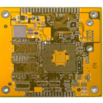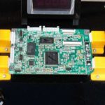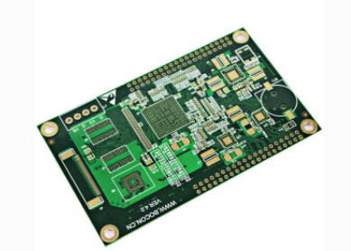
As electronic products continue to operate at higher speeds and frequencies, PCB Impedance has become an increasingly important consideration in PCB design and manufacturing. Impedance is particularly critical in high-speed digital, RF, microwave, and other signal-sensitive applications where even small variations in transmission-line geometry or dielectric properties can affect signal quality.
However, PCB impedance is sometimes misunderstood as simply the resistance of a circuit board. In practice, Characteristic Impedance and DC resistance are different electrical concepts.
DC resistance describes the opposition to direct current, while characteristic impedance describes the electrical behavior of a transmission line as a signal propagates through the PCB. For high-speed circuits, maintaining the required impedance within an appropriate tolerance is essential for reliable signal transmission.
So, what exactly is PCB impedance? Why does controlled impedance matter? And how do PCB materials, copper geometry, plating, and surface finishing affect impedance performance?
What Is PCB Impedance?
PCB Impedance is the electrical impedance presented by a PCB transmission line to a propagating signal.
For a controlled-impedance transmission line, the impedance is determined by multiple physical and material parameters, including:
- Trace width
- Copper thickness
- Dielectric thickness
- Dielectric constant (Dk)
- Trace geometry
- Distance to the reference plane
- Copper surface roughness
- Transmission-line structure
- Manufacturing tolerances
Common PCB transmission-line structures include microstrip, stripline, and various differential transmission-line configurations.
The objective is not simply to make impedance as low as possible. Instead, the PCB must be designed and manufactured to achieve the target impedance specified for the application.
For example, a high-speed interface may require a specific single-ended or differential impedance. The PCB stackup and trace geometry must therefore be designed to achieve that target within an acceptable tolerance.
PCB Impedance vs. DC Resistance
One of the most important concepts to understand is the difference between Characteristic Impedance and DC resistance.
DC resistance is primarily related to the resistivity and physical dimensions of the conductor. It affects power loss and voltage drop, particularly in power distribution and low-frequency circuits.
Characteristic impedance, however, describes how a transmission line interacts with a propagating signal.
For a simplified transmission-line model:
Z₀ ≈ √(L/C)
where:
- Z₀ is characteristic impedance
- L is inductance per unit length
- C is capacitance per unit length
In an actual PCB, these electrical parameters are strongly influenced by trace geometry and dielectric materials.
Therefore, a PCB with very low conductor resistance does not automatically have the correct characteristic impedance.
This distinction is especially important for high-speed PCB design.
Why Does Controlled Impedance Matter?
Controlled Impedance is used to maintain predictable signal transmission characteristics across a PCB.
When impedance is properly controlled, the transmission line can better match the connected components and interfaces. When significant impedance discontinuities occur, part of the signal energy can be reflected.
These reflections can cause problems such as:
- Signal distortion
- Ringing
- Overshoot and undershoot
- Timing errors
- Increased electromagnetic interference
- Reduced signal margins
- Data transmission failures
For high-speed interfaces, impedance control is therefore closely related to Signal Integrity.
Controlled impedance becomes increasingly important as signal rise times become faster, even when the nominal clock frequency itself may not appear extremely high.
What Determines PCB Impedance?
Several PCB design and manufacturing parameters affect impedance.
1. Trace Width
Trace width is one of the most important factors affecting transmission-line impedance.
For a given PCB stackup, changing the trace width changes the electromagnetic field distribution and therefore changes the characteristic impedance.
Manufacturing variation in trace width can consequently result in impedance variation.
2. Copper Thickness
Copper thickness affects conductor geometry and therefore contributes to impedance behavior.
The copper thickness used in the final PCB may include the base copper foil and additional plated copper. The actual finished conductor profile should therefore be considered during controlled-impedance design.
3. Dielectric Thickness
The distance between the signal trace and its reference plane has a significant effect on impedance.
A thinner dielectric spacing generally changes the coupling between the signal trace and reference plane. Therefore, dielectric thickness must be controlled carefully when manufacturing impedance-sensitive PCBs.
4. Dielectric Constant
The dielectric constant, or Dk, of the PCB material affects electromagnetic propagation through the dielectric.
Different materials and resin/glass configurations may exhibit different effective Dk values. At high frequencies, material selection becomes particularly important because variations in Dk can affect impedance and propagation delay.
5. Trace Geometry
The actual cross-sectional shape of a PCB conductor is also important.
In practical PCB manufacturing, copper traces are not always perfectly rectangular. Etching and plating can produce sidewall profiles that differ from the nominal CAD geometry.
This is particularly relevant for fine-line and high-frequency PCBs.
6. Copper Surface Roughness
At high frequencies, current tends to concentrate near the conductor surface due to the skin effect.
As a result, copper surface roughness can contribute to insertion loss and affect high-frequency signal performance. For demanding High-Speed PCB and high-frequency applications, copper foil selection and surface characteristics should therefore be considered during material selection and design.
Does Copper Plating Affect PCB Impedance?
Copper plating can affect impedance, but it should not be treated as the sole or primary determinant of PCB characteristic impedance.
During PCB Manufacturing, copper plating changes the final conductor thickness and geometry. If the finished copper thickness differs significantly from the value assumed during design, the resulting transmission-line impedance may also change.
This is particularly important for:
- Fine-line circuits
- High-frequency PCBs
- RF circuits
- Narrow differential pairs
- Edge-coupled structures
- High-density interconnects
Therefore, controlled-impedance fabrication requires coordination between the PCB designer and manufacturer.
The manufacturer should understand the target impedance, stackup, copper thickness, dielectric thickness, and acceptable manufacturing tolerance before production.
The Role of PCB Surface Finish
A PCB Surface Finish is applied primarily to protect exposed copper, improve solderability, and provide a suitable interface for component assembly.
Common surface finishes include:
- ENIG
- ENEPIG
- OSP
- HASL
- Immersion Tin
- Immersion Silver
Surface finish selection should be based on solderability, reliability, environmental requirements, contact requirements, cost, and application conditions.
It is not technically accurate to assume that the surface finish alone determines the overall PCB characteristic impedance.
For most controlled-impedance designs, the dominant factors are the transmission-line geometry, dielectric structure, material properties, and manufacturing tolerances.
Nevertheless, conductor thickness and surface characteristics associated with the final manufacturing process can contribute to high-frequency electrical performance and should be considered in demanding applications.
Why Surface Finish Quality Still Matters
Although PCB Surface Finish is not the primary parameter defining characteristic impedance, poor surface treatment can still create other electrical and reliability problems.
An appropriate surface finish should provide:
- Good solderability
- Stable surface protection
- Adequate copper protection
- Reliable component attachment
- Consistent manufacturing quality
Problems such as oxidation, contamination, poor adhesion, uneven coating, or surface defects can affect soldering and long-term reliability.
Therefore, surface finish should be evaluated as part of the overall PCB quality and reliability strategy rather than being incorrectly treated as a simple impedance-control parameter.
Impedance Control in High-Speed PCB Design
For a High-Speed PCB, impedance should be considered during the stackup and layout stages rather than after the PCB has already been designed.
Engineers should define the target impedance based on the interface requirements and then work backward to determine suitable:
- Trace widths
- Trace spacing
- Dielectric thickness
- Copper thickness
- Reference-plane configuration
- PCB material
- Differential-pair geometry
For differential signals, both the differential impedance and the individual conductor geometry must be considered.
Consistent spacing between differential traces is particularly important because changes in coupling can alter differential impedance.
Impedance Tolerance and Manufacturing Capability
A controlled-impedance design is only effective when the PCB manufacturer can reproduce the required structure consistently.
Manufacturing variables that may affect impedance include:
- Trace-width variation
- Copper-thickness variation
- Dielectric-thickness variation
- Etching characteristics
- Layer registration
- Material Dk variation
- Copper surface profile
- Lamination process variation
For this reason, impedance control should be treated as a combination of design engineering and process control.
The nominal CAD dimensions alone do not guarantee the final impedance.
How Is PCB Impedance Tested?
Manufacturers can verify impedance using appropriate test methods and test coupons.
A controlled-impedance test coupon is typically designed to represent the critical transmission-line structure used on the production PCB.
Testing may be performed using techniques such as time-domain reflectometry (TDR), depending on the product requirements and manufacturing standards.
The test results can be compared with the specified impedance target and tolerance.
For high-performance products, impedance verification provides an additional layer of manufacturing control and helps identify deviations before boards are shipped.
PCB Impedance and Signal Integrity
Signal Integrity depends on more than impedance alone.
Other important factors include:
- Trace length
- Return-current paths
- Via structures
- Layer transitions
- Connector geometry
- Crosstalk
- Power integrity
- Dielectric loss
- Copper roughness
- Manufacturing tolerances
An impedance-controlled PCB should therefore be designed as part of a complete signal-integrity strategy.
For high-speed interfaces, designers should also minimize unnecessary discontinuities and provide continuous reference planes wherever possible.
Common Misunderstandings About PCB Impedance
Several misconceptions about impedance can lead to incorrect PCB design or manufacturing decisions.
Misunderstanding 1: Lower resistance always means better impedance
Not necessarily.
Low DC resistance can be beneficial for reducing conductor loss and voltage drop, but high-speed transmission lines must meet their specified characteristic impedance rather than simply minimizing resistance.
Misunderstanding 2: Surface finish determines PCB impedance
Surface finish can influence the final conductor structure and high-frequency losses in some situations, but it is not the primary factor determining characteristic impedance.
Misunderstanding 3: The PCB manufacturer can change impedance after fabrication
Impedance is largely determined by the PCB stackup and trace geometry. Once the board has been fabricated, there is limited ability to correct a fundamental impedance-design error.
Therefore, impedance requirements should be established before manufacturing.
Misunderstanding 4: Simulation alone guarantees impedance
Simulation provides a valuable prediction, but actual manufacturing tolerances can cause deviations from the nominal design.
For critical applications, simulation should be combined with manufacturing capability evaluation and impedance testing.
Kingda’s Approach to Controlled Impedance
At Kingda, controlled-impedance PCB production is approached as a coordinated process involving PCB design, material selection, stackup engineering, circuit fabrication, lamination, copper processing, and inspection.
For impedance-sensitive applications, the key parameters are evaluated before production begins.
These may include:
- Target impedance
- Trace width and spacing
- Finished copper thickness
- Dielectric thickness
- Material Dk
- Reference-plane configuration
- Manufacturing tolerances
- Impedance test requirements
By connecting design specifications with actual manufacturing capabilities, Kingda helps customers achieve more consistent impedance performance for high-speed and high-frequency PCB applications.
Conclusion
PCB Impedance is an important electrical characteristic for high-speed and high-frequency circuit boards, but it should not be confused with simple DC resistance.
The required Characteristic Impedance is determined by the transmission-line structure, including trace geometry, dielectric thickness, material properties, copper thickness, and reference-plane configuration.
Reliable Controlled Impedance therefore requires close coordination between PCB design and PCB Manufacturing.
By selecting suitable materials, controlling trace geometry and dielectric dimensions, managing manufacturing tolerances, and verifying impedance through appropriate testing, engineers can improve Signal Integrity and achieve more reliable high-speed PCB performance.
For modern electronic products, impedance control is not simply a PCB fabrication detail. It is an important part of the overall electrical, manufacturing, and reliability strategy.