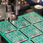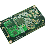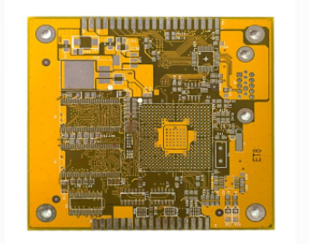
As electronic products continue to become smaller, thinner, and more highly integrated, conventional PCB structures are increasingly challenged by limited routing space and higher interconnection density requirements. HDI PCB technology has therefore become an important solution for modern compact electronic products.
HDI stands for High-Density Interconnect. An HDI PCB uses advanced microvia, fine-line, and high-density interconnection technologies to provide more electrical connections within a limited board area.
Compared with conventional multilayer PCBs, HDI technology can reduce via size, improve routing density, shorten electrical connection paths, and provide greater flexibility for high-density component packages such as fine-pitch BGAs.
Among the most important technologies used in HDI manufacturing are Blind Vias, Buried Vias, and laser-drilled microvias.
What Is an HDI PCB?
An HDI PCB is a high-density printed circuit board manufactured using advanced interconnection technologies that allow more routing and connections to be integrated into a smaller area.
HDI technology is particularly useful for products that require:
- High component density
- Fine-pitch BGA packages
- Smaller PCB dimensions
- More routing channels
- Reduced via sizes
- Shorter interconnection paths
- Compact and lightweight designs
HDI boards are widely used in smartphones, wearable devices, telecommunications equipment, automotive electronics, medical devices, industrial electronics, aerospace systems, and other high-density electronic applications.
A typical HDI structure may incorporate Microvias, fine lines and spaces, sequential lamination, and high-precision laser drilling.
What Is a Blind Via?
A Blind Via is a conductive via that connects an outer layer of the PCB to one or more inner layers without passing completely through the board.
For example, a via connecting Layer 1 to Layer 2 is commonly represented as a 1–2 blind via.
Unlike a conventional plated through-hole, a blind via has a defined termination layer and is not visible as a through-hole extending from one side of the PCB to the other.
Why Are Blind Vias Used?
Blind vias help PCB designers save routing space and improve interconnection density.
They are particularly useful beneath or around fine-pitch components where conventional through-holes would consume valuable routing channels.
Laser-drilled microvias are commonly used for short interlayer connections in advanced HDI PCB designs.
What Is a Buried Via?
A Buried Via connects two or more internal PCB layers without extending to the outer surface of the board.
Because the via is located entirely within the multilayer structure, it cannot normally be seen from the external surfaces of the finished PCB.
For example, a buried via connecting Layer 3 and Layer 4 can provide an internal connection without occupying an outer-layer pad.
Buried vias can increase routing flexibility in multilayer PCB designs, but they also make the manufacturing process more complex because the relevant inner layers must be drilled and interconnected before the final board structure is completed.
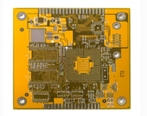
Blind Vias vs. Buried Vias
Although both technologies are used for high-density interconnection, they serve different purposes.
| Feature | Blind Via | Buried Via |
|---|---|---|
| Connection | Outer layer to inner layer | Inner layer to inner layer |
| Extends to surface | Yes | No |
| Common application | HDI and high-density routing | Multilayer internal interconnection |
| Manufacturing complexity | High | High |
| Laser drilling | Common for microvias | Depends on structure |
| Visibility on finished surface | Opening/pad may be visible | Normally not visible |
It is important to note that a PCB containing buried vias is not automatically an HDI PCB. HDI classification depends on the overall interconnection technology and manufacturing structure rather than the presence of one specific via type alone.
Likewise, not every HDI PCB must use buried vias. The actual structure depends on routing requirements, component density, layer count, board thickness, manufacturing capability, and cost targets.
Why Is HDI Technology Becoming More Important?
Modern portable electronics are moving toward smaller form factors and higher functionality. As a result, designers need to accommodate more electrical connections within increasingly limited PCB areas.
Fine-pitch BGA packages are a typical example.
When BGA pitch becomes smaller, conventional through-hole vias may consume too much routing space or interfere with component pads. Microvias and laser-drilled blind vias can provide shorter and more localized interconnections, making it easier to route signals from high-density component areas.
The major benefits of HDI technology include:
- Higher wiring density
- Smaller via dimensions
- Improved utilization of PCB space
- Greater routing flexibility
- Shorter electrical paths
- Better support for fine-pitch components
- Potential reduction in overall PCB size
HDI PCB Structure and Order
HDI structures are often described using concepts such as first-order, second-order, and higher-order HDI.
These terms generally relate to how blind vias are formed through sequential build-up and how many sequential HDI build-up cycles are incorporated into the PCB structure.
However, the exact layer connections are determined by the specific stackup and manufacturing design. Therefore, a first-order or second-order HDI structure should not be interpreted as one universal layer configuration.
First-Order HDI
A typical first-order HDI structure may use laser-drilled blind vias connecting adjacent layers near the outer surfaces.
For example, in a six-layer PCB, a structure may include:
1–2 and 5–6 blind vias
In this case, the laser-drilled microvias provide connections between the outer layers and their adjacent inner layers.
The exact structure can vary according to the customer’s routing requirements and the PCB manufacturer’s process capability.
Second-Order HDI
Second-order HDI uses additional sequential build-up and laser-drilling operations to create more complex interlayer connections.
A simplified manufacturing concept may involve:
Sequential Lamination → Laser Drilling → Additional Build-Up → Laser Drilling → Final Lamination/Processing
The actual layer-to-layer connections depend on the selected stackup.
Second-order HDI can provide greater routing flexibility than a basic first-order structure, but it also requires tighter process control and generally involves higher manufacturing complexity.
Staggered and Stacked Microvias
Advanced HDI designs can use either staggered or stacked microvia structures.
Staggered Microvias
In a staggered structure, microvias are arranged with an offset between adjacent layers rather than being directly aligned.
This approach can reduce certain manufacturing challenges and is commonly used when the PCB design allows sufficient routing space.
Stacked Microvias
In a stacked structure, microvias on different layers are vertically aligned.
Stacked microvias can provide highly efficient vertical interconnection and are useful for very high-density applications.
However, stacked structures require more precise manufacturing control because via alignment, copper filling, dielectric thickness, plating quality, and interlayer reliability become increasingly important.
For advanced stacked structures, copper-filled microvias may be used to create a reliable interconnection between sequential layers.
Laser Drilling in HDI Manufacturing
Laser Drilling is one of the key technologies enabling modern HDI structures.
Unlike conventional mechanical drilling, laser drilling can create very small microvias with high positional accuracy.
Common laser systems include UV laser and CO₂ laser technologies. The appropriate laser source depends on the dielectric material, copper structure, via dimensions, and required manufacturing process.
The laser-drilling process must carefully control parameters such as:
- Laser energy
- Pulse width
- Beam diameter
- Drilling depth
- Material absorption
- Copper thickness
- Resin characteristics
- Hole-wall quality
Poor laser process control can result in defects such as incomplete resin removal, excessive material damage, poor hole-wall quality, or unreliable metallization.
Sequential Lamination in HDI Manufacturing
Sequential Lamination is another important part of advanced HDI manufacturing.
Unlike a conventional multilayer PCB that may be laminated in a single major cycle, sequential build-up processes allow additional dielectric and copper layers to be added in stages.
A simplified concept is:
Core Fabrication → Build-Up Layer Formation → Laser Drilling → Copper Plating → Additional Build-Up → Laser Drilling → Final Lamination and PCB Processing
The actual sequence depends on the HDI stackup.
Sequential lamination requires accurate control of:
- Layer registration
- Dielectric thickness
- Resin flow
- Lamination temperature
- Pressure
- Curing conditions
- Thermal expansion
- Via-to-pad alignment
Registration accuracy becomes especially important as the number of sequential build-up cycles increases.
HDI Manufacturing Challenges
Although HDI technology provides significant design advantages, it also places higher demands on HDI Manufacturing.
1. Registration Accuracy
Small microvias and fine-line structures leave less tolerance for layer misalignment. Accurate registration is essential for reliable interconnection.
2. Laser Drilling Quality
The laser must remove the intended dielectric material without causing excessive damage to the surrounding structure.
3. Copper Plating Reliability
After drilling, the microvia must be properly metallized. Poor plating can cause open circuits, voids, or reliability problems during thermal cycling.
4. Via Reliability
Microvias experience thermal and mechanical stress during PCB fabrication, assembly, and product operation. Via geometry, copper thickness, dielectric properties, and material selection therefore require careful control.
5. Fine-Line Fabrication
HDI designs frequently use narrower traces and spaces than conventional PCBs. Imaging, etching, copper thickness, and process compensation must be tightly controlled.
HDI PCB Design Considerations
HDI technology should be considered from both design and manufacturing perspectives.
Before selecting an HDI structure, engineers should evaluate:
- BGA pitch
- Via diameter
- Pad diameter
- Trace width and spacing
- Layer count
- PCB thickness
- Dielectric thickness
- Stackup configuration
- Microvia structure
- Sequential lamination requirements
- Manufacturing tolerances
- Electrical performance
- Reliability requirements
Designers should also communicate with the PCB manufacturer at an early stage.
A structure that is technically possible in theory may not be the most economical or reliable solution for mass production. Working with a manufacturer that has proven HDI capabilities can help optimize the design before fabrication begins.
Is Every Board with Blind and Buried Vias an HDI PCB?
Not necessarily.
The presence of a Blind Via or Buried Via alone does not automatically define a PCB as an HDI board.
HDI is a broader manufacturing and interconnection technology involving factors such as microvias, fine-line circuitry, high-density routing, sequential build-up, and advanced fabrication processes.
For example, a multilayer PCB may contain buried vias but still be manufactured using a conventional multilayer process. Conversely, an HDI PCB may use laser-drilled blind microvias without requiring buried vias.
Therefore, the correct classification should be based on the complete PCB structure and manufacturing process.
Kingda’s HDI PCB Manufacturing Capabilities
At Kingda, HDI manufacturing is supported by process control across laser drilling, sequential lamination, microvia formation, copper plating, fine-line fabrication, and layer registration.
For high-density applications, the PCB structure should be selected according to the component pitch, routing requirements, electrical performance, reliability requirements, and production volume.
A well-planned HDI design can help reduce board size while providing sufficient routing channels for advanced semiconductor packages.
Kingda works with customers to evaluate stackup structures and manufacturing requirements during the engineering stage, helping ensure that the selected HDI solution is both technically feasible and suitable for stable production.
Conclusion
HDI PCB technology provides an effective solution for modern electronic products that require smaller dimensions, higher component density, and more complex interconnections.
Blind Vias, Buried Vias, and Microvias enable designers to create more efficient vertical interconnections, while Laser Drilling and Sequential Lamination provide the manufacturing foundation for advanced HDI structures.
As PCB designs move toward finer lines, smaller vias, tighter registration tolerances, and increasingly complex stackups, close coordination between PCB design and HDI Manufacturing becomes essential.
By selecting the appropriate via structure, stackup, materials, and manufacturing process, engineers can achieve higher routing density while maintaining PCB reliability, manufacturability, and overall product performance.