In PCB Assembly, accurate temperature control is essential for achieving reliable solder joints and consistent product quality. A Reflow Soldering process must provide sufficient heat to melt the solder paste and form reliable solder joints while preventing excessive thermal stress on components and the PCB.
For this reason, PCB Temperature Profiling is an important process-control method used to evaluate the actual temperature experienced by the PCB as it passes through the Reflow Oven. A properly measured thermal profile helps engineers verify whether the heating, soaking, reflow, and cooling stages are operating within the required process window.
Why PCB Temperature Profiling Is Necessary
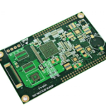
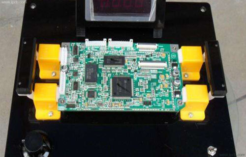
When testing a reflow profile, the thermocouple must measure the temperature at specific locations on the actual PCB assembly. An unassembled PCB cannot always provide a practical way to secure thermocouple measurement points in the same configuration as the production board.
Therefore, thermal profiling should generally be performed using a representative production assembly or a dedicated profiling board that accurately reproduces the thermal characteristics of the actual product.
Test boards should also not be exposed to repeated high-temperature cycles unnecessarily. Although a board may sometimes be returned to production after one or two profiling cycles when the process conditions remain within the material and component specifications, repeated thermal exposure can gradually affect solder joints, finishes, materials, and component reliability.
For this reason, a dedicated profiling sample is recommended whenever possible, particularly during production qualification, process optimization, or repeated reflow-profile verification.
Factors That Can Affect Temperature Measurements
The appearance and material composition of a PCB can influence how it responds to heat. A Reflow Oven primarily transfers heat through forced convection, although radiation also contributes to the overall thermal environment.
Dark-colored surfaces can absorb more radiant energy than lighter surfaces. However, this does not mean that a dark PCB will always produce an artificially high thermocouple reading. The measured temperature depends on the combined effects of convection, radiation, board construction, copper distribution, component density, and thermocouple attachment.
Therefore, engineers should not determine the reflow profile based solely on PCB color. The actual board temperature must be measured at representative locations.
For lead-free Reflow Soldering, this is particularly important because the required peak temperature and process window are generally higher and narrower than those used with many traditional leaded solder processes. An incorrectly configured thermal profile can result in insufficient solder melting, poor wetting, component damage, or excessive thermal stress.
1. Selecting PCB Temperature Test Points
The selection of Thermocouple locations is one of the most important steps in PCB Temperature Profiling.
The number of test points depends on the complexity of the PCB assembly and the number of available channels on the thermal profiler. In many applications, at least three representative points should be selected to identify the thermal variation across the board:
- Hot spot: A location expected to reach a relatively high temperature.
- Typical or average point: A location representing the general thermal behavior of the PCB.
- Cold spot: A location expected to heat more slowly or reach a lower temperature.
The actual locations should be determined according to the board layout and thermal characteristics rather than using fixed positions.
Typical cold spots may include:
- Large components with significant thermal mass
- Large copper areas
- Ground or power planes with high copper density
- Areas close to conveyor rails
- Board edges or locations with reduced airflow
- Areas where forced-air convection is partially obstructed
- Large connectors, shields, or other thermally massive structures
Hot spots may occur in areas with high exposure to heated airflow, lower thermal mass, or limited copper heat spreading.
The objective is to capture the temperature range experienced by critical parts of the PCB rather than simply collecting data from convenient locations.
2. Attaching the Thermocouples
The thermocouple measurement point must have good thermal contact with the PCB or component surface.
Depending on the application, thermocouples can be attached using a suitable high-temperature soldering method, high-temperature adhesive, or specialized thermocouple attachment materials.
When soldering a thermocouple directly to a pad or test point, the attachment material must be compatible with the expected process temperature and must not interfere with the soldering process.
When using high-temperature adhesive tape, the tape must provide sufficient mechanical strength and temperature resistance throughout the entire Reflow Oven cycle.
Regardless of the attachment method, the following requirements should be met:
- The thermocouple junction must remain firmly attached.
- The measurement point must have good thermal contact.
- The thermocouple should not move during conveyor transport.
- The attachment method should not significantly alter the thermal characteristics of the measurement location.
- Thermocouple wires should be routed so that they do not interfere with components, conveyor rails, or the oven.
Poor thermocouple attachment can result in delayed temperature response or inaccurate measurements, making the resulting thermal profile unreliable.
3. Connecting and Identifying the Thermocouples
Connect the thermocouples to the corresponding channels of the thermal profiler according to the equipment manufacturer’s instructions.
Polarity must be checked carefully to prevent incorrect temperature readings.
Each thermocouple should also be assigned a clear identification number. The corresponding number and physical location should be recorded on the PCB assembly or in the process documentation.
For example:
| Thermocouple | Measurement Location | Purpose |
|---|---|---|
| T1 | Small SMD area | Monitor typical board temperature |
| T2 | Large copper area | Monitor potential cold spot |
| T3 | Large component | Monitor thermal mass |
| T4 | Board edge | Evaluate edge temperature |
| T5 | Critical component | Verify component thermal exposure |
Clear identification makes it easier to compare the measured profile with component specifications and the solder paste manufacturer’s recommended process window.
4. Placing the PCB Assembly on the Reflow Oven Conveyor
Place the prepared PCB assembly on the Reflow Oven conveyor according to the normal production orientation.
If a thermal profiler is used, the data logger should be positioned securely behind or alongside the PCB according to the profiler manufacturer’s recommendations. Sufficient clearance must be maintained to prevent the logger from interfering with the oven entrance, conveyor system, or other equipment.
The PCB should pass through the oven using the same conveyor speed and process configuration intended for production.
The following parameters should be recorded:
- Conveyor speed
- Zone temperatures
- Soak time
- Time above liquidus
- Peak temperature
- Heating rate
- Cooling rate
- Board orientation
- Product configuration
Maintaining consistent process conditions is essential for obtaining meaningful thermal-profile data.
5. Monitoring the Real-Time Temperature Profile
During the test, the thermal profiler records temperature data from each thermocouple as the PCB travels through the oven.
When the profiling system supports real-time monitoring, the temperature curves can be displayed on the screen as the PCB moves through the different heating zones.
Engineers should pay attention to the temperature difference between measurement points. A large temperature variation may indicate uneven heat transfer caused by copper distribution, component density, board thickness, airflow, or oven settings.
The objective of thermal profiling is not simply to achieve the highest possible temperature. Instead, the profile should remain within the recommended process window for the solder paste, PCB materials, and components.
6. Retrieving the PCB and Analyzing the Thermal Profile
After the PCB passes through the reflow and cooling zones, carefully remove the PCB and thermal profiler.
Allow the assembly to cool sufficiently before handling the thermocouple wires or disconnecting the test equipment.
The recorded data can then be transferred to the profiling software for analysis.
Important parameters typically include:
- Peak Temperature
- Time Above Liquidus (TAL)
- Heating Rate
- Soak Time
- Cooling Rate
- Temperature Uniformity
- Minimum and maximum temperatures across test points
The measured values should be compared with the solder paste manufacturer’s recommended reflow profile and the maximum temperature limits of the PCB materials and components.
Evaluating the Reflow Soldering Profile
A good Thermal Profiling result should provide sufficient energy for the solder paste to melt and form reliable solder joints while keeping the entire assembly within its allowable thermal limits.
If the temperature is too low, potential problems include:
- Incomplete solder melting
- Poor wetting
- Insufficient solder joint formation
- Increased risk of soldering defects
If the temperature is too high or the exposure time is excessive, potential problems include:
- Component damage
- PCB material degradation
- Excessive intermetallic growth
- Delamination risk
- Solder mask or surface-finish degradation
- Excessive thermal stress
For lead-free soldering, engineers should pay particular attention to the process window because the soldering temperature requirements can be relatively demanding.
Improving PCB Temperature Uniformity
If significant temperature differences are observed across the PCB, several factors should be investigated.
PCB Copper Distribution
Large copper areas can absorb and spread heat differently from low-copper-density regions. An unbalanced copper distribution may contribute to thermal differences across the board.
Component Density
Large or thermally massive components can require more energy to reach the target temperature than small SMD components.
PCB Thickness and Layer Count
Board thickness, multilayer construction, copper distribution, and dielectric materials can all affect heat transfer.
Conveyor and Airflow Conditions
Board orientation, conveyor position, rail configuration, and airflow can influence the temperature profile.
Reflow Oven Settings
Zone temperature settings and conveyor speed should be adjusted systematically rather than changing individual parameters without evaluating the complete profile.
Best Practices for PCB Temperature Profiling
To obtain reliable results, PCB Temperature Profiling should follow a controlled and repeatable procedure:
- Use a representative production PCB assembly or dedicated profiling board.
- Select measurement points based on thermal characteristics and component requirements.
- Secure each Thermocouple firmly.
- Verify thermocouple channel identification and polarity.
- Record the location of every measurement point.
- Run the board using the intended production conveyor speed.
- Record heating, soaking, reflow, and cooling characteristics.
- Compare the profile with the solder paste manufacturer’s recommended window.
- Check the thermal limits of sensitive components.
- Repeat profiling whenever major materials, components, PCB construction, or oven parameters change.
Kingda’s Approach to PCB Temperature Control
At Kingda, thermal profiling is treated as an important part of process verification rather than simply a one-time temperature measurement.
By evaluating representative PCB locations, component thermal requirements, copper distribution, and reflow parameters together, engineers can identify potential hot spots and cold spots before they develop into production soldering problems.
Combining PCB Temperature Profiling with solder paste control, stencil optimization, component placement, PCB design, and Reflow Soldering process management helps create a more stable PCB Assembly process.
Conclusion
Accurate temperature measurement is essential for controlling the reflow soldering process. Proper selection of Thermocouple locations, secure attachment, representative test boards, controlled oven conditions, and systematic profile analysis can significantly improve soldering consistency.
Rather than focusing only on peak temperature, engineers should evaluate the complete thermal profile, including heating rate, soak behavior, time above liquidus, peak temperature, cooling rate, and temperature uniformity.
With effective PCB Temperature Profiling and appropriate process controls, manufacturers can establish a stable Reflow Soldering window, reduce soldering defects, protect temperature-sensitive components, and improve overall PCB assembly reliability.