2.5 Mil Fine Line PCB
Circuit density has become an important indicator of PCB performance as electronic products continue to become smaller and more integrated. A 2.5 Mil Fine Line PCB provides exceptionally precise circuit geometry, allowing electrical interconnections to be placed within a highly compact area. This capability provides an important hardware foundation for chip-scale packaging, high-density interconnects, and advanced electronic systems.
By reducing trace width and spacing, fine-line PCB technology allows more independent electrical paths to be integrated into a limited board area. This is particularly valuable for compact communication modules, medical electronics, industrial equipment, aerospace systems, and other products where board space and interconnection density are critical design factors.
Technical Characteristics of Fine Line PCB Technology
Breakthrough in Circuit Geometry
A 2.5 mil trace is approximately 0.0635 mm wide, placing extremely demanding requirements on circuit imaging, etching, copper thickness, dimensional stability, and manufacturing control.
In advanced applications, the trace width and spacing may both be designed around 2.5 mil, creating a 2.5 mil/2.5 mil line-and-space configuration. Such fine geometry can significantly increase routing density compared with conventional PCB structures and create additional space for components and interconnections.
For high-density electronic products, fine-line fabrication can also work together with advanced multilayer and microvia technologies. This allows engineers to accommodate more connections without proportionally increasing board dimensions.
GOPCBA’s published manufacturing capabilities include advanced HDI features such as microvias, stacked microvias, copper-filled microvias, and fine-pitch interconnection structures.
Signal Transmission Considerations
Fine traces have a smaller conductor cross-sectional area, which introduces additional considerations for electrical performance.
A narrower trace can have higher DC resistance when other parameters remain unchanged. Copper thickness, conductor geometry, copper quality, and current requirements therefore need to be evaluated during the design and manufacturing stages.
At higher frequencies, trace geometry also affects impedance, propagation behavior, insertion loss, and crosstalk. Narrow spacing can increase electromagnetic coupling between adjacent conductors, making reference planes, grounding structures, routing topology, and impedance control increasingly important.
For demanding applications, High Frequency PCB technology may be required. High-frequency PCB manufacturing involves coordinated control of dielectric properties, copper roughness, trace dimensions, layer registration, lamination, and impedance.
For high-speed circuits, maintaining predictable transmission paths is equally important. Continuous reference planes and carefully controlled stack-ups can help reduce reflection, crosstalk, and signal-integrity problems.
Balancing Electrical and Mechanical Reliability
Extremely fine traces must provide both electrical continuity and sufficient mechanical reliability.
High-ductility copper foil can be considered where mechanical flexibility or repeated thermal cycling is a concern. Trace geometry should also avoid unnecessary sharp corners, while appropriate routing transitions can help reduce localized mechanical stress.
During thermal cycling and reliability testing, properly manufactured fine-line circuits should maintain stable electrical characteristics. Copper adhesion, plating quality, laminate selection, and thermal expansion behavior all contribute to long-term reliability.
Precision Control During Fine Line PCB Manufacturing
Substrate and Copper Foil Selection
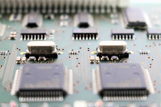
Material selection is one of the foundations of fine-line PCB manufacturing. The substrate should provide consistent thickness, good dimensional stability, and a sufficiently smooth surface for high-resolution circuit formation.
For conventional applications, glass-reinforced epoxy laminates may be used. For high-frequency applications, specialized low-loss materials such as PTFE-based laminates or other high-performance dielectric systems can be selected according to the required electrical characteristics.
GOPCBA supports a range of PCB technologies, including multilayer, HDI, high-frequency, high-speed, rigid-flex, and controlled-impedance PCB manufacturing.
Copper foil selection is equally important. Thin copper foil can provide advantages for high-density circuit formation, while surface treatment and copper profile influence both adhesion and high-frequency electrical performance.
At high frequencies, copper surface roughness becomes increasingly significant because of the skin effect. Lower-profile copper can help reduce conductor loss in demanding high-frequency applications.
Critical Technologies for Circuit Formation
Imaging and Development
High-resolution imaging technology is essential when producing 2.5 mil circuit geometries. Laser direct imaging or other high-precision imaging technologies can accurately transfer the circuit pattern onto the copper surface.
The photoresist must provide sufficient resolution and dimensional stability to reproduce extremely narrow traces and spaces. Development parameters also require careful control because excessive spray pressure or uneven development can damage fine photoresist structures.
Process stability is particularly important because even small dimensional deviations can have a significant effect when the designed trace width is only a few mils.
Precision Etching
Etching is one of the most critical processes in fine-line PCB manufacturing.
The manufacturing process must account for lateral etching, copper thickness, etchant chemistry, temperature, spray pressure, and etching time. Excessive lateral etching can reduce the final trace width and create undercutting, while insufficient etching can leave unwanted copper between adjacent traces.
Etch compensation can therefore be incorporated into the circuit design to compensate for predictable manufacturing variation.
Stable etching equipment, chemical control, process monitoring, and dimensional inspection are essential for achieving repeatable fine-line results.
Specialized Inspection and Quality Control
Fine-line PCBs require inspection methods capable of identifying defects that may be difficult to detect through conventional visual inspection.
Automated optical inspection can scan the circuit pattern at high resolution and identify defects such as open circuits, shorts, insufficient copper, trace breaks, and abnormal geometries.
Inspection algorithms should be configured according to the actual trace width and spacing to reduce both missed defects and unnecessary false positives.
Cross-sectional analysis provides another important method of verification. Samples can be cut, polished, and examined under a metallographic microscope to measure actual trace dimensions, copper thickness, dielectric thickness, plating quality, and other critical characteristics.
For high-frequency applications, impedance testing can additionally verify whether the manufactured transmission lines remain within the specified impedance range.
GOPCBA emphasizes process control across PCB fabrication, including material management, manufacturing, inspection, DFM review, and quality assurance.
Applications of 2.5 Mil Fine Line PCBs
Smartphone RF and Communication Modules
Modern wireless devices require high-density interconnections within increasingly compact modules. In 5G RF front-end systems, fine-line PCB structures can provide dense connections between antennas, RF components, filters, and processing devices.
A 2.5 Mil Fine Line PCB can provide additional routing capacity within a limited module footprint while supporting controlled electrical paths for high-frequency signals.
For advanced wireless communication systems, fine-line technology can be combined with high-frequency materials, controlled impedance, multilayer construction, and HDI interconnections.
Miniature Medical Electronics
Miniaturized medical electronics can benefit from high-density PCB technology because multiple sensors, control circuits, and communication components may need to fit within a very small enclosure.
Fine-line structures can help reduce routing space and support compact electronic assemblies. Depending on the device architecture, fine-line PCB technology can be combined with flexible or rigid-flex structures to accommodate mechanical constraints.
For medical electronics requiring high reliability, PCB manufacturing should also consider material consistency, electrical testing, dimensional control, cleanliness, and process traceability.
Industrial Robot Vision Systems
Industrial vision systems generate large quantities of image data that must move between image sensors, processors, memory devices, and communication interfaces.
A high-density PCB can provide sufficient routing capacity within compact camera and processing modules. Fine-line traces can help accommodate a large number of signal connections while preserving valuable board space for components and power-distribution structures.
For high-speed image interfaces, signal integrity becomes particularly important. Trace geometry, reference planes, impedance, via structures, and return-current paths should be considered together rather than treating trace width as an isolated parameter.
Aerospace and Navigation Electronics
Aerospace navigation and communication equipment often requires compact, lightweight, and reliable electronic assemblies.
Fine-line PCB technology can increase routing density while helping reduce the overall footprint of electronic modules. In RF navigation systems, the PCB must additionally maintain predictable high-frequency characteristics and stable mechanical performance under temperature variation and vibration.
For demanding aerospace applications, PCB design and manufacturing may require tighter control of material properties, dimensional tolerances, electrical performance, and manufacturing traceability.
Combining Fine Lines with HDI Technology
Fine-line fabrication becomes even more powerful when combined with HDI PCB technology.
HDI technology uses microvias, blind vias, buried vias, and sequential buildup structures to create more interconnections within a limited PCB area. Fine lines allow routing channels to become narrower, while microvias reduce the space required for layer-to-layer transitions.
This combination is particularly useful for fine-pitch BGAs, compact processors, RF modules, mobile electronics, and other high-density assemblies.
GOPCBA’s HDI capabilities include minimum microvia sizes down to 75 µm in its listed advanced capability range, together with stacked microvias and copper-filled microvias. Actual manufacturability should always be confirmed against the specific stack-up and design requirements.
For complex multilayer designs, via placement and spacing must also be carefully controlled. Excessively small spacing between vias, traces, and pads can create challenges during drilling, plating, layer alignment, and fabrication.
Design and Manufacturing Considerations
Achieving a reliable 2.5 mil circuit is not simply a matter of selecting a high-resolution imaging machine. The entire manufacturing chain must work together.
Important factors include:
- Trace width and spacing
- Copper thickness
- Copper surface profile
- Laminate dimensional stability
- Dielectric thickness
- Layer registration
- Imaging resolution
- Photoresist performance
- Etch compensation
- Etching uniformity
- Via dimensions
- Pad geometry
- Impedance requirements
- Surface finish
- AOI inspection
- Cross-sectional analysis
- Electrical testing
For multilayer boards, lamination and layer registration are particularly important. Small alignment errors can accumulate across multiple layers and affect fine traces, vias, pads, and interconnections.
A controlled Multilayer PCB Manufacturing Process should therefore coordinate inner-layer fabrication, inspection, registration, lamination, drilling, plating, outer-layer circuit formation, and final testing.
For high-density structures, the lamination process must also maintain accurate layer alignment and minimize internal defects.
The Importance of Prototype Validation
Before moving a 2.5 mil design into larger-scale production, prototype validation can help identify manufacturing and electrical risks.
A prototype allows engineers to evaluate actual trace dimensions, layer registration, impedance, via quality, solderability, component assembly, and mechanical compatibility.
This is particularly important when a design combines fine lines with HDI, high-frequency materials, microvias, or high layer counts.
GOPCBA provides PCB Prototype Manufacturing to help engineers validate PCB designs before production scaling.
Prototype testing can reveal problems early, allowing the design or manufacturing process to be adjusted before larger production quantities are released.
Conclusion
The development of 2.5 mil fine-line PCB technology represents an important advancement in high-density electronic manufacturing. By reducing trace width and spacing, manufacturers can create more routing capacity within smaller PCB footprints and support increasingly compact electronic systems.
However, successful Fine Line PCB manufacturing depends on much more than circuit imaging. Substrate selection, copper foil characteristics, imaging resolution, etching control, layer registration, inspection, impedance testing, and process stability all contribute to the final result.
When combined with HDI PCB, multilayer, and High Frequency PCB technologies, 2.5 mil circuit structures can support sophisticated applications ranging from wireless communication and medical electronics to industrial robotics and aerospace systems.
As semiconductor packaging and electronic integration continue to advance, PCB trace dimensions may become even smaller. This will place greater demands on materials, imaging, etching, registration, inspection, and manufacturing process control.
Professional fine-line PCB manufacturing will therefore remain an important foundation for the next generation of compact, high-performance, and high-density electronic products.
For projects requiring advanced fine-line, HDI, high-frequency, or multilayer PCB fabrication, customers can review GOPCBA PCB Manufacturing Capabilities and work with an engineering team to evaluate the specific manufacturing requirements.