PCB Gold Fingers: Complete Design and Manufacturing Guide
The row of gold-colored conductive contacts found on computer memory modules, graphics cards, and other expansion boards is commonly known as a “gold finger.”
In PCB manufacturing, these contacts are also referred to as edge contacts or edge connectors. They provide a reliable electrical interface between a PCB and an external connector, allowing signals and power to pass between the PCB and another electronic system.
Because gold fingers are frequently inserted and removed, their mechanical durability, electrical reliability, surface finish, and dimensional accuracy are especially important.
This guide explains the function of PCB Gold Fingers, key design considerations, and the major manufacturing factors engineers should understand before production.
What Are PCB Gold Fingers?
PCB gold fingers are exposed conductive contacts located along the edge of a circuit board. They are designed to mate with a corresponding connector or slot.
Typical applications include:
- Computer memory modules
- Graphics cards
- Expansion cards
- Industrial control boards
- Communication modules
- Embedded electronic systems
- Other removable PCB assemblies
The edge-contact structure allows a secondary PCB to be inserted into a connector without requiring a separate cable connection.
Electrical Interconnection
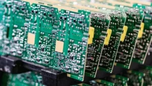
A gold finger PCB provides an electrical interface between the PCB and a connector.
For example, expansion cards can use edge contacts to connect signals between the card and the motherboard. Depending on the application, these contacts may carry:
- Power
- Ground
- Digital signals
- High-speed signals
- Control signals
- Communication interfaces
Replaceable and Modular PCB Connections
One important advantage of edge connectors is that they allow a PCB to be installed, removed, or replaced without permanently soldering it to another board.
This makes edge-contact designs useful for modular electronics such as memory cards, expansion cards, communication modules, and industrial control systems.
For applications requiring reliable manufacturing of specialized edge-contact boards, selecting a manufacturer with dedicated PCB Manufacturing capabilities is important.
PCB Gold Finger Design Considerations
Gold finger areas require more attention than ordinary PCB pads because they are exposed to both electrical contact and mechanical wear.
The design should therefore consider the board edge, bevel angle, solder mask, copper routing, pad geometry, and plating process together.
1. Gold Finger Bevel Design
A bevel is typically applied to the PCB edge containing the gold fingers.
The angled edge makes it easier to insert the PCB into its mating connector and reduces the mechanical force required during insertion.
A commonly used bevel angle is 45°, although the appropriate angle depends on the connector and PCB construction.
Keep a Safe Distance From the PCB Edge
The distance between the gold finger contacts and the board edge must account for:
- Finished board thickness
- Bevel angle
- Contact length
- Connector geometry
- Manufacturing tolerance
If the gold finger is positioned too close to the board edge, the beveling process may remove part of the contact area.
Therefore, the gold finger position should be calculated according to the actual board thickness and required bevel geometry.
For high-reliability products, these mechanical considerations should be reviewed during the PCB layout stage rather than being corrected after fabrication.
2. Solder Mask Opening for Gold Fingers
Gold fingers are normally exposed and should not be covered with conventional solder mask.
A solder mask layer over the contact area would interfere with the electrical connection between the PCB and its mating connector.
During repeated insertion and removal, solder mask in the contact area could also wear away and create contamination or reliability problems.
Key Solder Mask Considerations
The solder mask opening should completely expose the required gold finger contact area.
Engineers should verify:
- The complete contact area is exposed.
- The solder mask does not overlap the active contact region.
- The opening dimensions meet the manufacturer’s requirements.
- Adjacent copper does not become unintentionally exposed.
- Vias near the gold finger region are properly treated.
The exact solder mask expansion should be determined according to the PCB manufacturer’s process capability and the specific design rules rather than relying on a universal value.
For prototype designs, it is particularly important to verify the solder mask layer in the final Gerber data before production. GOPCBA’s rapid prototyping capabilities support multiple surface finishes, including ENIG, ENEPIG and gold-finger processes.
3. PCB Edge and Corner Design
The PCB edge around the gold finger area should be designed to support smooth insertion into the mating connector.
Sharp board corners can interfere with connector insertion and may damage the connector housing or contact structure.
A beveled edge is therefore commonly used on boards with edge contacts.
The exact edge treatment should be based on the connector specification and the required insertion direction.
Engineers should also make sure that the bevel does not reduce the effective gold finger contact length.
4. Copper Pour Near Gold Fingers
Copper pours should be carefully controlled around gold finger areas.
If multiple gold finger contacts belonging to the same electrical net are connected by an inappropriate copper pour on the outer layer, individual contacts may become electrically joined.
This can create an unintended continuous copper region rather than maintaining separate contact pads.
For this reason, the outer-layer copper geometry around the gold finger area should be reviewed carefully during PCB layout.
The goal is to maintain the intended electrical isolation and mechanical geometry of each individual contact.
5. Long and Short Gold Finger Design
Some edge connectors use staggered gold fingers with different lengths.
Long and short contacts can provide controlled connection and disconnection sequences during insertion.
For example, longer contacts may establish ground or other reference connections before shorter signal contacts engage.
When designing staggered contacts, engineers should carefully control:
- Contact length
- Trace routing
- Trace-to-pad spacing
- Pad geometry
- Transition from the gold finger into the PCB
- Corner geometry
When a trace transitions from the edge contact into the main PCB area, sharp 90-degree geometry should generally be avoided where it creates unnecessary mechanical or routing constraints.
A smooth or angled transition can provide a cleaner design and better manufacturability.
6. Gold Finger Panelization
Panelization requires additional attention when manufacturing PCBs with gold fingers.
The panel arrangement must provide enough space for:
- Gold finger plating connections
- Manufacturing tooling
- Beveling
- Routing
- Registration
- Electrical testing
Gold fingers should normally be oriented in a way that allows the plating process and electrical connections to be implemented efficiently.
For smaller boards, the manufacturing sequence may also require special consideration because beveling and final routing operations must be completed accurately without damaging the contact area.
The exact panelization method depends on the board dimensions, plating process, bevel requirements, and manufacturer’s production equipment.
PCB Gold Finger Manufacturing Process
After the design has been verified, the PCB enters the manufacturing process.
The exact production sequence varies depending on the board construction and selected surface finish, but a typical process may include:
Material Preparation → Inner-Layer Imaging → Etching → AOI → Lamination → Drilling → Copper Plating → Outer-Layer Imaging → Pattern Plating → Etching → Solder Mask → Surface Finish → Gold Finger Plating → Routing → Beveling → Electrical Testing → Final Inspection
Not every PCB requires every step, and some processes may be combined or performed in a different sequence.
The important point is that gold finger manufacturing requires dedicated process control beyond standard PCB fabrication.
Hard Gold Plating for Gold Fingers
The gold finger area is commonly finished with hard gold because the contacts must withstand repeated mechanical insertion and removal.
Hard Gold Plating typically consists of a nickel layer beneath a harder gold contact surface.
The nickel layer provides a diffusion barrier and supports the contact structure, while the gold surface provides corrosion resistance and stable electrical contact.
Because gold plating is relatively expensive, hard gold is normally applied selectively to areas that require repeated contact rather than across the entire PCB.
GOPCBA’s published PCB capabilities specifically include Gold Fingers, Flash Gold, Full Body Hard Gold, and other selective surface finishes.
Hard Gold vs. ENIG
Hard gold and ENIG should not be treated as interchangeable processes.
ENIG is widely used for solderable PCB pads because it provides a relatively flat surface and good solderability.
Hard gold is better suited to contact areas that experience repeated mechanical wear.
Therefore:
- ENIG is commonly used for soldering surfaces.
- Hard gold is commonly used for durable electrical contacts.
- Gold fingers generally require a surface finish selected specifically for repeated mating cycles.
The appropriate finish should always be selected according to the electrical, mechanical, and assembly requirements of the product.
PCB Gold Finger Manufacturing Quality Control
Gold fingers require inspection at multiple stages because even a small defect can affect connector engagement or long-term reliability.
Important inspection points include:
Dimensional Inspection
Check:
- Gold finger width
- Contact length
- Spacing
- Board thickness
- Bevel dimensions
- Edge position
- Overall PCB dimensions
Surface Inspection
The gold finger surface should be checked for:
- Scratches
- Plating voids
- Uneven plating
- Contamination
- Oxidation
- Surface damage
- Excessive discoloration
Electrical Inspection
Electrical testing should verify that the contact structure and associated PCB circuitry meet the required electrical specifications.
Mechanical Inspection
The beveled edge and board dimensions should be inspected to ensure that the PCB can be inserted into the intended connector without interference.
Gold Finger DFM Review Before Production
Because gold finger PCBs often involve additional plating, beveling, and dimensional requirements, design verification should be completed before production begins.
A professional DFM review can help identify issues such as:
- Insufficient edge clearance
- Incorrect solder mask openings
- Improper contact spacing
- Routing problems
- Inappropriate bevel geometry
- Panelization problems
- Manufacturing limitations
For new products, prototype manufacturing provides an opportunity to verify the mechanical fit and electrical performance of the gold finger before committing to larger production quantities.
GOPCBA’s prototype assembly workflow includes design review, PCB fabrication, component procurement, assembly, and testing, making prototype builds useful for identifying manufacturing problems before production.
Gold Finger PCB Manufacturing Checklist
Before releasing a gold finger PCB for production, engineers should verify the following:
Design
- Confirm the gold finger dimensions.
- Verify the contact spacing and length.
- Check the PCB edge clearance.
- Confirm the bevel angle and dimensions.
- Review long and short contact requirements.
- Check copper routing near the edge contacts.
Solder Mask
- Ensure the gold finger area is completely exposed.
- Verify solder mask clearance.
- Check for unintended exposed copper near the contacts.
- Review nearby via treatment.
Plating
- Specify the required gold finger plating process.
- Confirm the required nickel and gold thickness with the manufacturer.
- Ensure hard gold is applied only where required.
- Confirm that the plating method is compatible with the intended insertion cycles.
Panelization and Manufacturing
- Confirm the panel orientation.
- Provide adequate plating and tooling areas.
- Verify routing and bevel requirements.
- Confirm board thickness.
- Review manufacturing tolerances.
- Check the final production data before release.
Conclusion
Gold fingers are more than simply exposed gold-colored PCB pads. They are precision electrical and mechanical interfaces that must withstand repeated connector engagement while maintaining reliable electrical performance.
Successful Gold Finger PCB design requires careful coordination between PCB layout, solder mask, copper routing, board-edge geometry, panelization, plating, beveling, and inspection.
The surface finish is particularly important. Standard solderable finishes and contact finishes serve different purposes, so the plating process should be selected according to the actual mechanical and electrical requirements of the application.
Ultimately, reliable PCB Edge Connector performance begins during the design stage and continues through fabrication, plating, beveling, inspection, and final testing.
By reviewing the design for manufacturability before production and working with a manufacturer that has dedicated gold finger capabilities, engineers can reduce manufacturing risks and achieve more reliable edge-contact PCBs.