High-Current PCB Design Guide: How to Prevent PCB Burnout
No engineer wants to see a PCB catch fire, components smoke, or a board fail under load. Yet these problems can occur in high-power electronic equipment, especially when a PCB must continuously carry high currents.
When current density becomes too high, PCB traces can overheat, solder joints can deteriorate, and excessive thermal stress can eventually lead to catastrophic failure.
For power supplies, battery systems, industrial equipment, automotive electronics, and other high-power applications, choosing the right board structure is essential. One effective solution is to use a thick copper PCB and optimize the entire PCB design for current capacity and thermal management.
What Is a Thick Copper PCB?
A thick copper PCB is a printed circuit board manufactured with significantly thicker copper conductors than those used in standard PCBs.
In the industry, copper thickness of 2 oz or more is commonly associated with thick copper PCB technology. However, terminology and classification can vary between manufacturers and industry standards.
Thicker copper can be applied to both outer and inner layers of a multilayer PCB, depending on the current requirements and board construction.
The actual copper thickness should be selected according to factors such as:
- Required current
- Trace width
- Trace length
- Allowable temperature rise
- Layer configuration
- Thermal management requirements
- PCB manufacturing capabilities
- Mechanical and electrical requirements
For high-power applications, copper thickness should therefore be considered together with the overall PCB design, rather than treated as an isolated parameter.
Why Do High-Current Applications Need Thick Copper PCBs?
1. Thick Copper Provides Higher Current-Carrying Capacity
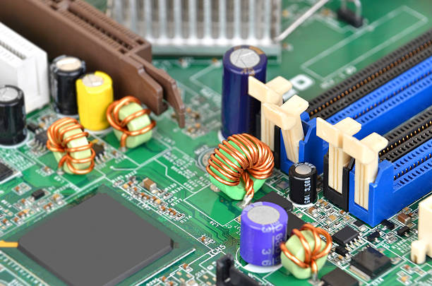
One of the primary reasons to use thick copper is its ability to carry higher current.
The resistance of a PCB trace can be expressed as:
R = ρL / S
Where:
- R is resistance
- ρ is the resistivity of the conductor material
- L is the trace length
- S is the cross-sectional area of the conductor
For a rectangular PCB trace:
S = W × H
Where:
- W is the trace width
- H is the copper thickness
When the trace width, length, material, and other conditions remain constant, increasing copper thickness increases the conductor cross-sectional area and reduces resistance.
This allows a thicker copper trace to carry more current while maintaining a lower temperature rise.
In practical high-current PCB applications, both copper thickness and trace width should be optimized according to the required current and allowable temperature rise.
2. Thick Copper Helps Improve Thermal Performance
Current flowing through a PCB trace generates heat because of electrical resistance.
The basic relationship can be expressed as:
P = I²R
Where:
- P is power dissipated as heat
- I is current
- R is resistance
When current increases, power dissipation increases rapidly. This is particularly important for power electronics because even a relatively small resistance can produce significant heat at high current.
Increasing copper thickness reduces trace resistance. As a result, less electrical energy is converted into heat under the same operating conditions.
A thicker copper layer can also provide a larger thermal conduction path, helping distribute heat away from high-current areas.
However, copper thickness alone does not guarantee adequate cooling. A complete thermal strategy may also require:
- Wider copper areas
- Large copper pours
- Thermal vias
- Heat sinks
- Proper component placement
- Appropriate PCB materials
- Adequate airflow
These factors should be considered during PCB design to prevent localized hot spots.
3. Thick Copper Helps Reduce Thermal Stress
Heat generation is another important factor affecting PCB reliability.
The heat generated by a conductor over a specific period can be expressed as:
Q = I²Rt
Where:
- Q is generated heat
- I is current
- R is resistance
- t is operating time
Because resistance decreases as the conductor cross-sectional area increases, increasing copper thickness can reduce heat generation under otherwise identical conditions.
Lower heat generation helps reduce temperature rise and thermal stress within the PCB.
This is particularly important for equipment that operates continuously at high current, where repeated heating and cooling cycles can contribute to material expansion, solder-joint fatigue, delamination, and other reliability problems.
Other Advantages of Thick Copper PCBs
In addition to higher current capacity and improved thermal performance, thick copper construction can provide several other benefits.
Higher Mechanical Strength
Thicker copper contributes to the overall robustness of the board and can be advantageous in applications exposed to mechanical or thermal stress.
Better Power Distribution
Thick copper layers can support large current paths and power distribution networks, making them suitable for high-power circuits and energy-intensive equipment.
More Compact High-Power Designs
Using appropriate copper thickness and optimized routing can help engineers achieve the required electrical performance without simply increasing the physical size of the PCB.
For complex power electronics, a combination of thick copper, multilayer construction, optimized routing, and appropriate thermal management can provide a more efficient solution.
Key Design Considerations for High-Current PCBs
Selecting thick copper is only one part of a reliable high-current design.
Optimize Trace Width and Copper Thickness
Increasing copper thickness does not eliminate the need for adequate trace width.
A narrow trace with thick copper may still experience excessive temperature rise if the current exceeds its allowable capacity.
Engineers should therefore evaluate copper thickness and trace width together based on the expected current and acceptable temperature rise.
Minimize High-Current Trace Length
Longer conductors have higher resistance.
Where possible, high-current paths should be kept short and direct. Unnecessary bends, narrow neck-down sections, and bottlenecks should also be avoided.
Use Copper Planes Where Appropriate
Large copper areas or planes can distribute current over a wider area and improve both electrical and thermal performance.
For multilayer boards, high-current paths can sometimes be distributed across multiple copper layers, depending on the stack-up and manufacturing capabilities.
Pay Attention to Vias and Connections
A high-current path is only as strong as its weakest section.
Vias, pads, connectors, solder joints, and other transition points can become current bottlenecks. When high current passes between PCB layers, the number, size, arrangement, and copper plating of vias should be carefully considered.
Consider Thermal Management During PCB Manufacturing
The selected copper thickness must also be compatible with the manufacturing process.
Heavy copper boards can require different etching, plating, lamination, and fabrication considerations compared with standard PCBs. Working with an experienced PCB manufacturing provider can help ensure that the intended copper thickness and board structure can be manufactured consistently.
Thick Copper PCB Applications
Thick copper technology is particularly useful in applications where high current, high power, or demanding thermal conditions are involved.
Typical applications include:
- Power supplies
- Battery management systems
- Energy storage systems
- Electric vehicles
- Automotive electronics
- Industrial power equipment
- Welding equipment
- Motor controllers
- Renewable energy systems
- Power converters
- High-power LED systems
- Industrial control equipment
For prototype and small-batch products, engineers can also combine thick copper PCB fabrication with prototype PCB assembly to verify electrical, thermal, and mechanical performance before moving into larger-scale production.
PCB Manufacturing and Assembly Considerations
A high-current board requires more than a suitable schematic.
The PCB fabrication process, component selection, soldering process, assembly technology, and testing procedures can all affect final product reliability.
For example, a high-power PCB may combine large copper areas with SMT components, through-hole components, connectors, and other high-current interfaces.
A reliable manufacturing workflow should therefore consider both PCB fabrication and assembly requirements from the beginning of the project.
For products that require different component technologies on the same board, mixed-technology PCB assembly can combine SMT and through-hole components within one manufacturing process.
Why PCBA Testing Matters for High-Current Applications
Even a well-designed PCB can fail if manufacturing defects or assembly problems remain undetected.
Potential issues may include:
- Insufficient solder joints
- Open or short circuits
- Incorrect component placement
- Poor solder wetting
- Manufacturing defects
- Connection resistance
- Component overheating
- Assembly-related electrical failures
For this reason, PCBA testing should be incorporated into the production process according to the requirements of the product.
Testing methods may include electrical testing, functional testing, visual inspection, automated optical inspection, and other verification procedures.
For high-power products, testing is especially important because a small manufacturing defect can become a significant failure when the board operates under high current.
Conclusion
A PCB designed for high current must be engineered around electrical current capacity, resistance, heat generation, and thermal management.
Using a thick copper PCB can provide several important advantages, including higher current-carrying capacity, lower conductor resistance, improved heat distribution, and reduced thermal stress.
However, copper thickness is only one part of the solution. A reliable high-current PCB also requires appropriate trace width, optimized routing, sufficient copper area, suitable vias, effective thermal management, and a manufacturing process capable of maintaining the required specifications.
For high-power electronic products, integrating these considerations from the earliest stage of PCB design can significantly improve reliability and reduce the risk of overheating and PCB burnout.
With proper PCB manufacturing, assembly, and PCBA testing, thick copper PCB technology can provide a practical and reliable foundation for demanding high-current applications.