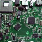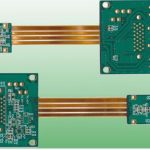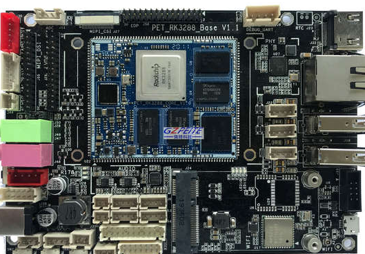
Solder Bridging is one of the most common soldering defects encountered during SMT Assembly, particularly around fine-pitch integrated circuits (ICs). It occurs when molten solder unintentionally connects two or more adjacent pads or component leads, creating an electrical short circuit.
The risk of bridging increases significantly as component pitch becomes smaller. Fine-pitch QFPs, QFNs, BGAs, and other high-density packages require precise solder paste deposition, accurate component placement, and carefully controlled reflow conditions.
For modern PCB Assembly, preventing Solder Bridging is important not only for electrical performance but also for production yield, reliability, and manufacturing cost.
This article explains the major causes of SMT solder bridging and practical solutions involving stencil design, solder paste, printing, component placement, and reflow soldering.
What Is SMT Solder Bridging?
Solder Bridging occurs when solder forms an unintended connection between adjacent conductive areas.
It is especially common between fine-pitch IC leads and pads. As the distance between adjacent pads decreases, even a small amount of excess solder or a slight printing offset can cause neighboring solder deposits to merge during reflow.
Typical symptoms include:
- Two adjacent pads connected by solder
- Short circuits between IC pins
- Excessive solder accumulation
- Solder beads around fine-pitch components
- Insufficient separation between solder joints
The probability of bridging depends on several variables, including pad geometry, stencil aperture design, solder paste properties, PCB surface condition, printing accuracy, component placement, and the reflow profile.
Main Causes of Solder Bridging
For fine-pitch components, Solder Bridging is usually not caused by one isolated process problem. It often results from the interaction of several factors.
The major contributors include:
- Improper stencil aperture design
- Excessive or poorly controlled solder paste deposition
- Printing misalignment
- Poor solder paste release
- Component placement problems
- Excessive solder-paste collapse during placement
- Incorrect reflow temperature profile
- PCB pad or land-pattern issues
- Contamination or poor surface condition
Effective defect prevention therefore requires process control across the entire SMT Processing workflow.
A. Stencil Design
Stencil Design is one of the most important factors in controlling solder paste volume and preventing bridging.
The stencil aperture must provide enough solder paste to create a reliable solder joint without depositing excessive solder between adjacent fine-pitch pads.
1. Area Ratio
For small apertures, the area ratio is an important consideration when evaluating solder paste release.
A commonly referenced guideline is an area ratio of approximately 0.66 or higher, although the appropriate value depends on the stencil technology, aperture geometry, solder paste, stencil thickness, and printing process.
For fine-pitch applications, simply meeting an area-ratio target is not sufficient. The complete aperture design must also be evaluated.
2. Smooth Aperture Walls
The inner walls of stencil apertures should be sufficiently smooth to promote consistent solder paste release.
Laser-cut stencils with appropriate finishing or electro-polishing can provide improved aperture-wall quality.
Poor aperture-wall conditions can cause solder paste to remain inside the stencil instead of transferring completely to the PCB pads.
3. Aperture Shape
For fine-pitch components, aperture geometry should be optimized to control solder volume and minimize the possibility of adjacent deposits merging.
Depending on the component package and pad geometry, aperture reductions, rounded corners, home-plate-style openings, or other modified geometries may be used.
The goal is to achieve sufficient solder-joint volume while maintaining adequate separation between neighboring pads.
4. Stencil Thickness
Stencil thickness should be selected according to the smallest component pitch, aperture dimensions, required solder volume, and the complete component mix on the PCB.
For fine-pitch ICs, thinner stencils may be necessary, but reducing thickness can also reduce solder volume for larger components.
Therefore, a single stencil thickness may require compromise across different package types. Step stencils or other specialized stencil structures may be considered for boards containing both fine-pitch and large-component requirements.
B. Solder Paste Selection
The correct Solder Paste is another important factor in preventing Solder Bridging.
For fine-pitch applications, solder paste with an appropriate powder particle size is generally preferred because it can provide better print definition and release.
For example, Type 4 or finer solder powders may be considered for fine-pitch assembly, depending on the component geometry and printing requirements.
Important solder-paste characteristics include:
- Powder particle size
- Viscosity
- Flux activity
- Tackiness
- Slump resistance
- Printability
- Storage stability
- Reflow characteristics
The solder paste should always be stored and handled according to the supplier’s specifications.
The selection of flux activity should also consider PCB surface condition, storage history, component requirements, and the intended assembly process.
There is no single solder paste formulation that is optimal for every PCB Assembly application.
C. SMT Printing
SMT Printing is a critical process because solder paste volume and positional accuracy are established before components are placed.
1. Squeegee Selection
Squeegees are commonly available in different materials and configurations.
For fine-pitch printing, metal squeegees are often preferred because they provide stable contact with the stencil and consistent paste rolling behavior.
The selection should consider stencil type, solder paste, printing equipment, and production requirements.
2. Squeegee Pressure
Squeegee pressure should be sufficient to wipe the stencil clean without unnecessarily deforming the stencil or forcing excessive solder paste through the apertures.
Too much pressure can increase paste leakage and accelerate stencil wear, while insufficient pressure may leave solder paste on the stencil surface.
The correct setting depends on the equipment, stencil, paste, and PCB.
3. Printing Speed
Printing speed influences solder paste rolling, stencil filling, and release.
If the speed is too high, the stencil apertures may not fill consistently. If the speed is too low, paste behavior and print quality may also be affected.
Typical production settings may fall within a broad range, but the optimal speed should be established through process validation rather than using one fixed value for every application.
4. Contact and Separation
Stencil printing can involve different separation approaches depending on the printer and process.
Controlled stencil separation is especially important for fine-pitch printing because poor separation can distort solder paste deposits.
The separation speed should be optimized to achieve clean paste release while minimizing deposit deformation.
5. PCB Support
Proper PCB support is often overlooked but can have a major influence on printing quality.
If the PCB flexes or moves during printing, the stencil-to-pad alignment can change, leading to uneven solder paste deposition and increasing the risk of bridging.
For fine-pitch assemblies, adequate tooling and support should therefore be used to maintain stable contact between the PCB and stencil.
D. Component Placement
Component placement can also contribute to Solder Bridging.
For fine-pitch components, placement accuracy must be sufficient to ensure that the component terminals align correctly with the solder paste deposits.
If a component is placed with excessive offset, the solder joints may become unbalanced during reflow.
Placement parameters that should be controlled include:
- X/Y position
- Rotation
- Placement height
- Placement force
- Component recognition
- Fiducial accuracy
The placement machine should also be properly calibrated for small components and fine-pitch packages.
Placement Height
Placement height should be optimized so that the component terminals make appropriate contact with the solder paste without excessively compressing the deposits.
Excessive compression can cause neighboring deposits to spread or merge before reflow.
Therefore, placement height and force should be determined according to the component package, PCB pad design, solder paste properties, and equipment specifications.
E. Reflow Soldering
Reflow Soldering is the final major process stage in which solder paste melts and forms permanent electrical and mechanical connections.
An inappropriate thermal profile can increase the probability of bridging and other soldering defects.
Potential causes include:
1. Excessive Heating Rate
If the board heats too quickly, the solder paste and flux may not behave as intended.
2. Excessive Peak Temperature
An excessively high peak temperature may affect component reliability, solder-joint quality, and flux performance.
3. Uneven Heating
If different areas of the PCB experience significantly different temperatures, solder may melt and wet at different rates.
4. Inappropriate Time Above Liquidus
The time above liquidus must be controlled according to the solder alloy and solder-paste manufacturer’s process window.
The correct reflow profile depends on:
- Solder alloy
- Solder paste
- PCB thickness
- Copper distribution
- Component thermal mass
- Board loading
- Reflow oven characteristics
Therefore, the reflow profile should be validated using actual production assemblies rather than relying on a universal temperature curve.
Other Factors That Can Cause Solder Bridging
PCB Pad Design
Poor pad geometry can increase the risk of solder bridging.
Pad dimensions should be compatible with the component manufacturer’s land pattern recommendations and the selected assembly process.
For fine-pitch packages, pad-to-pad spacing must provide sufficient separation after solder deposition.
PCB Surface Condition
Oxidation, contamination, moisture, or inappropriate surface-finish conditions can affect solder wetting and joint formation.
A clean and properly specified PCB surface is therefore important for consistent SMT Processing.
Component Coplanarity
If component terminals are not sufficiently coplanar, solder volume may distribute unevenly across the package.
This can create excessive solder at some terminals while producing insufficient solder at others.
How to Prevent Solder Bridging
A systematic prevention strategy should cover the entire assembly process.
1. Optimize Stencil Design
Use appropriate stencil thickness and aperture reductions for fine-pitch components.
2. Control Solder Paste Volume
Avoid excessive solder paste deposition while maintaining enough material for reliable solder joints.
3. Maintain Printing Accuracy
Regularly verify stencil alignment, PCB support, squeegee condition, and printing parameters.
4. Monitor Solder Paste Printing
SPI can be used to measure solder paste volume, height, area, and positional offset before component placement.
5. Optimize Component Placement
Maintain accurate placement position, rotation, height, and force.
6. Validate the Reflow Profile
Use thermocouples and profile measurements to verify that the PCB and components remain within the solder-paste process window.
7. Use AOI After Reflow
AOI can identify many visible bridging defects and other soldering problems before the PCB proceeds to later production stages.
8. Apply X-Ray Inspection When Appropriate
For hidden solder joints such as BGA connections, X-ray inspection may be necessary because optical inspection cannot directly view the joint.
Why Early Detection Matters
Detecting Solder Bridging as early as possible helps reduce production losses.
If a printing problem is discovered by SPI before placement and reflow, the affected PCB may be corrected before additional manufacturing steps are completed.
If the defect is discovered only after final testing, the manufacturer may need to perform:
- Troubleshooting
- Rework
- Component removal
- Solder removal
- Cleaning
- Re-inspection
- Electrical retesting
Early process monitoring therefore helps improve first-pass yield and reduce total manufacturing cost.
Kingda SMT Assembly Quality Control
Kingda provides SMT Assembly and PCB Assembly services with process controls designed to support reliable production across different component types and board structures.
Depending on project requirements, the manufacturing process can incorporate:
- Automated solder paste printing
- Solder paste inspection
- Precision component placement
- Controlled Reflow Soldering
- AOI Inspection
- X-ray inspection
- Electrical testing
- Functional testing
For fine-pitch and high-density PCB assemblies, Kingda’s engineering team can review stencil requirements, component placement, solder-paste selection, thermal profiles, and inspection requirements before production.
This process-oriented approach helps identify potential Solder Bridging risks at an early stage rather than relying solely on final inspection.
Conclusion
Solder Bridging is a common but preventable defect in modern SMT Assembly, especially when working with fine-pitch ICs and high-density PCB designs.
The most effective solution is not to adjust a single machine parameter. Instead, manufacturers should control the complete process, including Stencil Design, Solder Paste, SMT Printing, component placement, Reflow Soldering, and post-reflow inspection.
With appropriate DFM review, stable printing conditions, optimized solder-paste deposition, accurate component placement, and a validated reflow profile, the risk of bridging can be significantly reduced.
Kingda supports customers with PCB Assembly and SMT Processing solutions designed around the specific requirements of each PCB and electronic product.