




First Article Inspection in PCBA: Process and Benefits Guide
First article inspection in PCBA verifies that the first assembled board from a new production run matches the design files and BOM before the factory starts producing the full quantity. Also called FAI, this check prevents wrong components, reversed polarity, missing parts, and setup errors from turning into a large batch of defective boards. A quick first-article review before mass production can save hours of rework and protect the delivery schedule.
This guide explains the FAI process, the tools used for intelligent inspection, and why first article verification is an important part of PCBA quality control.
In a factory that runs many different products, the risk of setup error increases with every changeover. A small mistake in feeder loading or program selection can be repeated across an entire shift before anyone notices.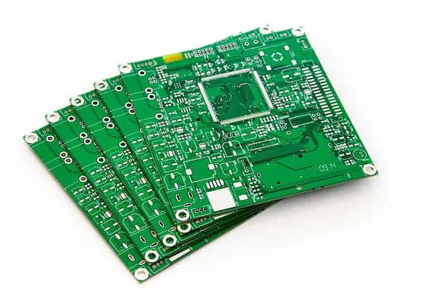
Why First Article Inspection Matters
Production setup mistakes can affect every board in the lot. A wrong reel loaded on the placement machine, an incorrect stencil, or a reversed component orientation may not be noticed until functional test fails on many boards.
FAI catches these errors while only one or a few boards have been produced. Correcting the setup at this point is much cheaper than reworking an entire batch.
It also protects the customer’s schedule. Discovering a defect after mass production can cause delays that affect the whole product launch.
FAI should also confirm that the correct board version is used. If a new revision changes pad locations or component values, the first article will show whether the assembly program and BOM match the new design.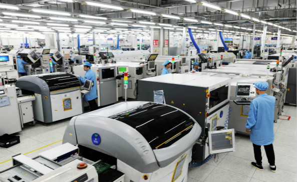
What FAI Checks
First article inspection verifies that the component value, package, polarity, position, and quantity match the BOM and design file. It also checks the PCB version, silkscreen, and assembly documentation.
Common errors found by FAI include wrong resistor values, swapped capacitors, reversed diodes, missing components, incorrect IC orientation, and mismatched component revisions that might otherwise pass electrical testing until the wrong value causes a subtle performance issue.
The check should be performed after the first board has passed reflow, because the final assembly state may be different from the placement program.
Intelligent FAI systems also reduce the risk of inspector fatigue. The machine performs the repetitive comparison work, while the operator focuses on confirming ambiguous results and deciding whether the defect is acceptable under the quality standard.
Manual versus Intelligent First Article
Traditional first article inspection relies on an operator comparing the board with a BOM and drawing by eye. This process is slow and can miss subtle errors on dense boards.
Intelligent FAI systems use OCR and image comparison to check component markings and package geometry automatically. They can detect a wrong resistor value or a rotated capacitor faster than manual review.
The result is higher accuracy and shorter inspection time, especially when a product contains many small components.
The operator should verify a sample of readable components during FAI, even when OCR reports a pass. This confirms that the system’s recognition threshold is correct and that the reference data has not been corrupted.
OCR Verification of Component Markings
OCR, or optical character recognition, reads the printing on resistors, capacitors, ICs, and other components. The recognized value is compared with the expected value from the BOM.
OCR is especially useful for resistors because their code changes with value and tolerance. It can also identify IC markings to confirm the correct part number.
OCR reliability depends on image quality, lighting, and component finish. The inspection system should be able to handle different marking styles and sizes.
The system should also check component height and shape where possible. A taller or shorter package may indicate the wrong component was placed even when the marking cannot be read clearly.
Image Comparison for Polarity and Missing Parts
For parts without readable markings, FAI can compare the component body shape, orientation, and pad position with the expected design. Image comparison detects missing parts and components that are reversed or rotated.
IC notches, diode bands, capacitor polarity marks, and crystal orientation are checked during this step. The software highlights suspicious areas for the operator to confirm.
This is especially important for packages that look similar but have different electrical behavior.
Data quality is the foundation of FAI. If the CAD file contains the wrong component location or the BOM lists an obsolete part, the first article may pass incorrectly. The supplier should validate reference data before the inspection run.
CAD and BOM Data Import
A good FAI system begins with correct reference data. The CAD coordinates, BOM, and PCB design files are loaded into the inspection system before the first board is scanned.
Using the CAD data lets the system know exactly where each component should be and what value or marking is expected. It also reduces manual programming time.
If the BOM or design is revised, the FAI program should be updated before the new production run starts.
The report should include clear images of inspected components, the pass or fail result, and the operator name. This record supports both the customer’s incoming quality review and the manufacturer’s internal corrective action process.
The Five-Step FAI Process
The first step is data import. The operator loads the customer drawing, CAD file, and BOM into the system.
The second step is automatic programming. The FAI software generates an inspection path for the board, so the operator does not need to define every location manually.
The third step is inspection. OCR and image comparison check the relevant components automatically, while the fourth step guides the operator through any items that need confirmation. The fifth step creates a full report for traceability.
FAI time can also be reduced by grouping inspections by component location. The operator follows the board in a logical path from one area to the next, avoiding unnecessary movement and repeated magnification changes.
How Long Does FAI Take?
A modern intelligent FAI can complete a typical PCBA first-article review in about 20 to 60 minutes. The exact time depends on board size, component count, and the number of uncertain locations that require human judgment.
Manual first article inspection may take longer and provide less consistent coverage. Investing in an automated FAI system reduces production startup time.
For high-mix production, the shorter setup time is valuable because each product changeover requires a new first article check.
FAI is especially important for products that will go directly to high-volume production. Fixing a setup problem after the first few panels is far less expensive than discovering it after hundreds of boards have been assembled.
FAI and Production Release
The first article must pass before the line is released for full production. If the board fails, the operator corrects the setup, builds another first article, and repeats the inspection.
The FAI report should be saved with the lot records under a controlled quality management system. It provides evidence that the product was verified before mass production and helps trace the cause of any later issue.
When the first article passes, the process parameters, component placement, and inspection results become the baseline for the production run.
For customers who order multiple product variants from the same factory, FAI becomes even more valuable. It confirms that the correct BOM and program are active for the specific product being built, preventing costly mix-ups between similar boards.
Benefits for Customers
Customers benefit from fewer batch defects, shorter delivery time, and better traceability. FAI reduces the risk of receiving an entire order with the wrong component or reversed polarity.
For high-reliability products, the first article report also supports the customer’s quality audit. The supplier can show that the design was verified before committing material and labor.
Prevention through FAI is cheaper than detection after mass production.
In-process data should also be compared with the FAI baseline. If placement accuracy, solder paste, or reflow results begin to drift during the run, the production team can stop and check whether the process is still aligned with the approved first article.
Integrating FAI with Other Quality Checks
FAI is the first check of a run, but it should be followed by SPI, AOI, X-ray, and functional testing. First article verification confirms the setup, while automated inspection protects every board in the lot.
A complete SMT PCB assembly process combines FAI with PCBA testing and controlled PCB manufacturing to maintain quality from the first board to the last.
First article inspection should be treated as a standard release gate for every new PCB assembly run, not only for complex boards. Even simple products can have wrong feeders, reversed parts, or an outdated program that creates a large batch defect.
The factory should also review FAI findings periodically to identify common setup mistakes and improve its changeover procedures. Over time, this reduces the number of first articles that fail and shortens the average production startup time.
Conclusion
First article inspection in PCBA is a fast, cost-effective way to prevent batch defects and improve production efficiency. OCR, image comparison, CAD data, and automatic reporting make the process more accurate than manual review alone.
By making FAI a standard part of production release, PCBA manufacturers can reduce waste, protect schedules, and deliver reliable boards to their customers.


