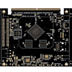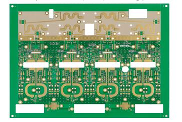
In printed circuit board design, electrical connections between components and conductive structures are primarily established through solder pads. A pad is one of the most fundamental elements of PCB layout and plays a critical role in component assembly, electrical connectivity, thermal management, and manufacturing reliability.
For a high-frequency PCB or microwave PCB, pad design becomes even more important because pad geometry can affect not only soldering quality but also impedance, parasitic capacitance, signal integrity, and RF performance.
Depending on the component type and assembly process, PCB pads can generally be divided into two major categories: non-via pads and via pads.
Non-via pads are primarily used for surface-mount components, while via pads are associated with through-hole components or structures where a via is incorporated into the pad. In advanced PCB designs, via-in-pad technology may also be used to support fine-pitch components and high-density interconnections.
The appropriate pad shape and size should be selected according to the component package, lead geometry, electrical requirements, manufacturing tolerances, soldering process, thermal conditions, and mechanical stress.
1. Types of PCB Pads
Modern PCB design software provides a variety of standard pad geometries, including round, rectangular, square, octagonal, and custom-shaped pads.
The correct geometry depends on the component footprint and the intended manufacturing process.
1.1 Round Pads
Round pads are among the most commonly used types of PCB pads.
They are frequently used for:
- Through-hole component leads
- Test points
- Alignment points
- Reference points
- Mechanical connection structures
- General-purpose connection points
For a through-hole pad, the key dimensions include the finished hole diameter and pad diameter.
The pad diameter should provide an adequate annular ring around the finished hole while accounting for drilling tolerance, registration accuracy, plating requirements, and reliability requirements.
For high-frequency PCB applications, unnecessary pad area should generally be avoided around sensitive RF structures because larger conductive areas can introduce additional parasitic effects.
1.2 Octagonal Pads
Octagonal pads are less common than round or rectangular pads but can be useful in specific PCB layouts.
Their geometry can provide a balance between routing flexibility and soldering area.
Octagonal pads may be considered when the designer needs to:
- Improve routing clearance
- Maintain sufficient solderable area
- Optimize conductor spacing
- Reduce unnecessary copper area
The appropriate geometry should be determined according to the component footprint and manufacturing requirements rather than selected simply for appearance.
1.3 Custom-Shaped Pads
Special applications may require custom-shaped pads.
For example, pads carrying high current or experiencing significant thermal or mechanical stress may use enlarged or specialized geometries.
A teardrop structure is another commonly used technique in PCB design. A teardrop pad gradually widens the connection between a pad and its trace or via.
It can help improve mechanical strength and manufacturing robustness, particularly around small pads and drilled holes.
However, teardrops should be used according to the design requirements and should not interfere with high-frequency routing or impedance control.
1.4 Rectangular and Square Pads
Rectangular pads are widely used for surface-mount component terminals.
Their dimensions are normally determined by the component manufacturer’s recommended footprint and the selected soldering process.
Square pads may also be used to identify a particular pin, such as Pin 1, when the component package and PCB assembly convention require visual differentiation.
For SMD components, pad length, width, spacing, solder-mask clearance, and component-to-pad relationship must all be carefully controlled.
2. PCB Pad Size and Land Size
PCB pad size has a significant influence on soldering quality, assembly yield, electrical performance, and long-term reliability.
There is no universal pad dimension that can be applied to every component.
Pad dimensions should be determined by considering:
- Component package dimensions
- Component dimensional tolerances
- Lead dimensions
- Recommended land pattern
- Solder-joint requirements
- PCB manufacturing tolerances
- PCB assembly capability
- Soldering process
- Component placement accuracy
- Required reliability level
For standard components, the component manufacturer’s recommended land pattern should normally be used as the starting point.
The design can then be adjusted according to the capabilities of the PCB fabricator and assembly manufacturer.
3. Factors Affecting PCB Pad Size
When determining PCB pad size, designers should consider both the component and the manufacturing process.
Component Dimensions
The first consideration is the actual component package.
Different packages require different pad geometries. For example:
- QFP packages use closely spaced rectangular pads.
- QFN packages require carefully defined perimeter pads and exposed thermal pads.
- BGA packages use arrays of circular or specialized pads.
- Chip resistors and capacitors require pads sized according to their package dimensions.
- Through-hole components require pads surrounding the drilled holes.
Therefore, the footprint should always be compatible with the actual component package.
Manufacturing Tolerance
PCB fabrication introduces dimensional tolerances.
Etching, drilling, registration, copper plating, solder-mask application, and surface finishing can all affect the final pad geometry.
For high-density designs, these tolerances become increasingly important.
A pad that appears sufficiently large in CAD may become difficult to manufacture if the available annular ring or clearance is too small.
Assembly Capability
PCB assembly equipment also affects pad design.
The designer should consider:
- Pick-and-place accuracy
- Solder-paste printing accuracy
- Stencil design
- Reflow profile
- Component placement tolerance
- Solder-mask registration
- Inspection capability
A good pad design must be compatible with both PCB fabrication and assembly.
4. Solder Mask Clearance and Pad Geometry
Pad design does not only involve the copper land itself.
The solder mask opening around the pad also affects assembly performance.
Depending on the design requirements, pads may be configured as:
- Solder-mask-defined pads
- Non-solder-mask-defined pads
The choice depends on component type, pitch, manufacturing capability, and reliability requirements.
For fine-pitch devices, solder-mask registration must be carefully controlled to prevent unintended solder bridging or insufficient solder coverage.
In a high-frequency PCB, solder-mask geometry can also influence the electrical environment around RF traces and pads. Therefore, solder-mask openings should be considered as part of the complete RF layout rather than as an isolated manufacturing detail.
5. Pad Design for High-Frequency and Microwave PCBs
Pad design becomes more sensitive as operating frequency increases.
For a microwave PCB, the pad is not simply a soldering structure. It can become part of the electrical transmission path.
An oversized pad may increase parasitic capacitance, while an improperly shaped pad can introduce impedance discontinuities.
When designing RF and microwave structures, engineers should evaluate:
- Pad dimensions
- Trace width
- Ground clearance
- Via placement
- Reference-plane structure
- Dielectric thickness
- Copper thickness
- Component package
- Signal frequency
For example, an RF transmission line connected to a component should transition smoothly between the trace, pad, and component terminal.
Abrupt changes in conductor width or reference-plane geometry may increase discontinuity and degrade signal integrity.
6. Via Pads and Through-Hole Pads
Via pads are commonly associated with plated holes that provide electrical connections between PCB layers.
For through-hole components, the pad surrounds the finished hole and provides the soldering interface.
The main design parameters include:
- Finished hole diameter
- Pad diameter
- Annular ring
- Plated copper thickness
- Clearance to surrounding copper
- Component lead diameter
The required annular ring should account for manufacturing tolerances and reliability requirements.
For HDI and high-density applications, via dimensions can become much smaller, and designers may use microvias, blind vias, buried vias, or via-in-pad structures.
7. Via-in-Pad Design
Via-in-pad technology places a via directly inside a component pad.
It is particularly useful for high-density packages such as BGAs and advanced semiconductor devices.
The major advantages include:
- Shorter electrical connections
- Reduced routing length
- Higher routing density
- Improved power distribution
- Better use of PCB space
However, via-in-pad requires appropriate manufacturing technology.
If the via is not properly filled and capped, solder paste may flow into the via during reflow, resulting in insufficient solder volume or solder-joint defects.
Therefore, via pads used in via-in-pad structures should be designed together with the via-filling and surface-finishing process.
8. Thermal Pads and High-Current Applications
Some components require large exposed pads for thermal dissipation or high-current conduction.
Power semiconductor devices, voltage regulators, LEDs, and RF power components are common examples.
For these applications, the pad may be connected to a large copper area or multiple thermal vias.
Thermal-via arrays can transfer heat from the component into an internal or bottom copper plane.
However, too many open vias directly beneath a soldered component can allow solder to escape during reflow.
Therefore, thermal-pad design must consider:
- Via diameter
- Via pitch
- Via filling
- Solder-paste coverage
- Copper area
- Thermal requirements
- Assembly process
9. Do Not Rely on a Single Universal Pad Formula
There is no single mathematical formula that can reliably determine the optimum PCB pad size for every application.
Pad dimensions are influenced by multiple variables, including component tolerance, PCB fabrication capability, assembly equipment, soldering technology, reliability requirements, and design standards.
Therefore, designers should not directly copy pad dimensions from another PCB project without verifying their applicability.
A better approach is to establish an internal footprint library based on:
- Component manufacturer recommendations
- Applicable industry standards
- PCB fabrication capability
- PCB assembly capability
- Product reliability requirements
- Design verification and manufacturing feedback
This approach creates a controlled and reusable footprint database.
10. Understand PCB Material and Manufacturing Capability
A good PCB pad design must match the capabilities of the PCB manufacturer.
Before finalizing the footprint, designers should understand the characteristics of the selected PCB substrate, including:
- Material type
- Dimensional stability
- Thermal stability
- Copper thickness
- Surface finish
- Minimum trace width
- Minimum spacing
- Minimum hole size
- Registration accuracy
- Solder-mask capability
For a high-frequency PCB, material selection is particularly important because dielectric properties and dimensional stability can influence RF performance.
High-frequency and microwave applications may also require specialized laminate systems with controlled dielectric constant and low dissipation factor.
11. Understand Component Packaging and Thermal Characteristics
Although many component packages follow international standards, differences may still exist among manufacturers.
Two components with the same nominal package designation may have slightly different terminal dimensions, recommended footprints, thermal characteristics, or assembly requirements.
Therefore, designers should always verify the latest component datasheet before creating or modifying a footprint.
For critical applications, it is also useful to consider:
- Component operating temperature
- Maximum power dissipation
- Thermal pad requirements
- Solder-joint reliability
- Mechanical stress
- Component tolerance
These factors directly influence pad geometry.
12. Consider PCB Assembly Equipment
Pad dimensions must also match the capabilities of the assembly line.
Important equipment-related factors include:
- Pick-and-place accuracy
- Stencil printing accuracy
- Solder-paste volume control
- Reflow capability
- Automatic optical inspection
- X-ray inspection
- Dispensing accuracy
If the pad geometry is too aggressive for the available assembly process, manufacturing yield may decrease even when the PCB itself can be fabricated successfully.
Therefore, PCB fabrication and assembly capabilities should be considered together during the footprint design stage.
13. PCB Pad Design Checklist
Before releasing a PCB design for production, engineers can review the following items:
- Confirm the component package dimensions.
- Verify the manufacturer’s recommended footprint.
- Check pad length and width.
- Check pad-to-pad spacing.
- Verify solder-mask clearance.
- Confirm via and hole dimensions.
- Check annular-ring requirements.
- Evaluate thermal-pad design.
- Review high-frequency signal transitions.
- Check impedance continuity.
- Verify manufacturing tolerances.
- Confirm PCB assembly capability.
- Review solder-paste requirements.
- Perform DFM verification.
This systematic review can significantly reduce manufacturing and assembly problems.
14. Kingda PCB Manufacturing Support
Kingda provides PCB manufacturing solutions for standard and advanced electronic applications, including multilayer, high-density, high-frequency, and microwave circuit boards.
For projects requiring specialized PCB pads, Kingda can work with customers to evaluate pad dimensions, hole structures, via-in-pad requirements, surface finishing, impedance control, and manufacturing tolerances.
For high-frequency PCB and microwave PCB applications, the pad design should be evaluated together with the complete stack-up and RF transmission structure.
By combining design verification, material selection, manufacturing process control, and inspection, Kingda helps customers develop PCB solutions that balance electrical performance, assembly efficiency, reliability, and manufacturability.
Conclusion
PCB pad design is a fundamental part of PCB engineering, but it involves much more than simply defining a copper shape.
Pad geometry and PCB pad size affect soldering quality, electrical performance, thermal management, manufacturing yield, and long-term reliability.
For conventional boards, pad dimensions should primarily match the component package and assembly process. For high-frequency PCB and microwave PCB applications, designers must also consider impedance, parasitic effects, signal transitions, grounding, and RF performance.
A reliable pad design process should therefore integrate component specifications, PCB material characteristics, fabrication tolerances, assembly capabilities, and product reliability requirements.
By establishing standardized footprints and verifying each design against actual manufacturing capabilities, engineers can achieve more consistent PCB quality and improve the overall performance and reliability of advanced electronic products.