SMT Assembly for Wearable ECG Recorders on Rigid-Flex Boards
A wearable ECG recorder has to fit signal acquisition, storage, communication and power management into a space the size of a wristband. The board that results carries small passives, QFN devices, board-to-board connectors and a flexible tail that reaches the electrodes, the buttons or the battery. Assembling it is not simply a matter of a machine with a tight placement specification; what decides the yield is how the board is supported, how the paste is printed, how the parts are oriented and how flat the assembly is after reflow.
Start with the Rigid-Flex Data
The data package for a rigid-flex board needs more than the usual set. Alongside the Gerber data, the bill of materials, the placement coordinates, the assembly drawing and the panel drawing, the project should include a drawing of the flexible region that marks the bend lines and the bend direction.
That drawing is not documentation. If the flexible tail connects to an electrode, a button or a battery, the bend direction, the orientation of the connector and the assembly keep-out zones around the flexible area all determine whether the finished assembly can be fitted into the product. Where a substitute part is permitted, the bill of materials should name the acceptable brands, models or key parameters, so that the decision is not made on the line while the machine is waiting.
When a project is imported, the first checks are comparisons: the designators in the bill of materials against the placement data, the number of placements against the component count, and the orientation in the assembly drawing against the footprint. The pin one marking on a QFN, a diode, a sensor and a connector is checked individually, because those are the parts whose rotation error cannot be corrected later. On a rigid-flex board there is a further check: whether the tooling holes, the panel edges and the rails can actually support printing and conveying, because a flexible tail with no reliable holding position lets the board move during the process, and correct coordinates do not put a part in the right place on a board that is shifting.
Why a Carrier Is Needed
A rigid board can be supported on tooling pins or a universal support. A board with a flexible tail cannot, because the tail can hang, lift or be dragged by a rail or by the movement of a nozzle. The tail is also the part of the assembly that is most sensitive to being handled.
The answer is a carrier fixture designed for the board. It holds the rigid area in one plane and constrains the flexible area without clamping the components or the pads, and it leaves the inspection and test positions accessible. Three requirements govern the design.
The carrier must not press on a pad, a component or a surface that will be inspected later. It must allow for the dimensional change of the assembly during reflow, which on a flexible material can be larger than on a rigid board, so a carrier that fits exactly at room temperature may grip the board at peak temperature. And it must be stable enough that the placement machine sees the same board position for every unit in the batch, because variation between units is indistinguishable from a machine error.
Paste Printing on Fine Pitch Pads
The printing stage is where a wearable assembly is won or lost. The areas that need attention are the fine pitch pads, the thermal pad under each QFN and the pins of the board-to-board connector.
A larger stencil aperture is not an improvement. Too much paste produces bridging between adjacent leads, or lifts the component on a bed of solder during reflow so that it drifts before the joint forms. Too little paste produces joints that look acceptable and are not reliable. For the large centre pad of a QFN, the aperture is evaluated as a set of windows rather than a single opening, because the area required for thermal transfer and the volume that can be released cleanly are two different numbers.
After printing, the deposit is checked for offset, insufficient paste, bridging and slumped edges. The check is done at this stage rather than after reflow because the correction is a wipe and a repeat, whereas the same defect found after reflow is a rework operation on a board that may not survive it.
Placement and the First Article
Before the feeders are loaded, the reel labels, the designator ranges, the component orientation and the package size are verified against the data. This is routine on any assembly, and it is more important here because the components are small and the reels look alike.
The first article inspection then has to look at more than whether the parts are placed. It should confirm that the flexible region has not moved relative to the carrier, that the connector orientation matches the mechanical drawing, and that the QFN and any sensor are rotated correctly. On a small batch, the first article is also the moment when the completeness of the design data becomes visible, so it is worth treating it as a review point rather than a formality.

Reflow and the Flexible Material
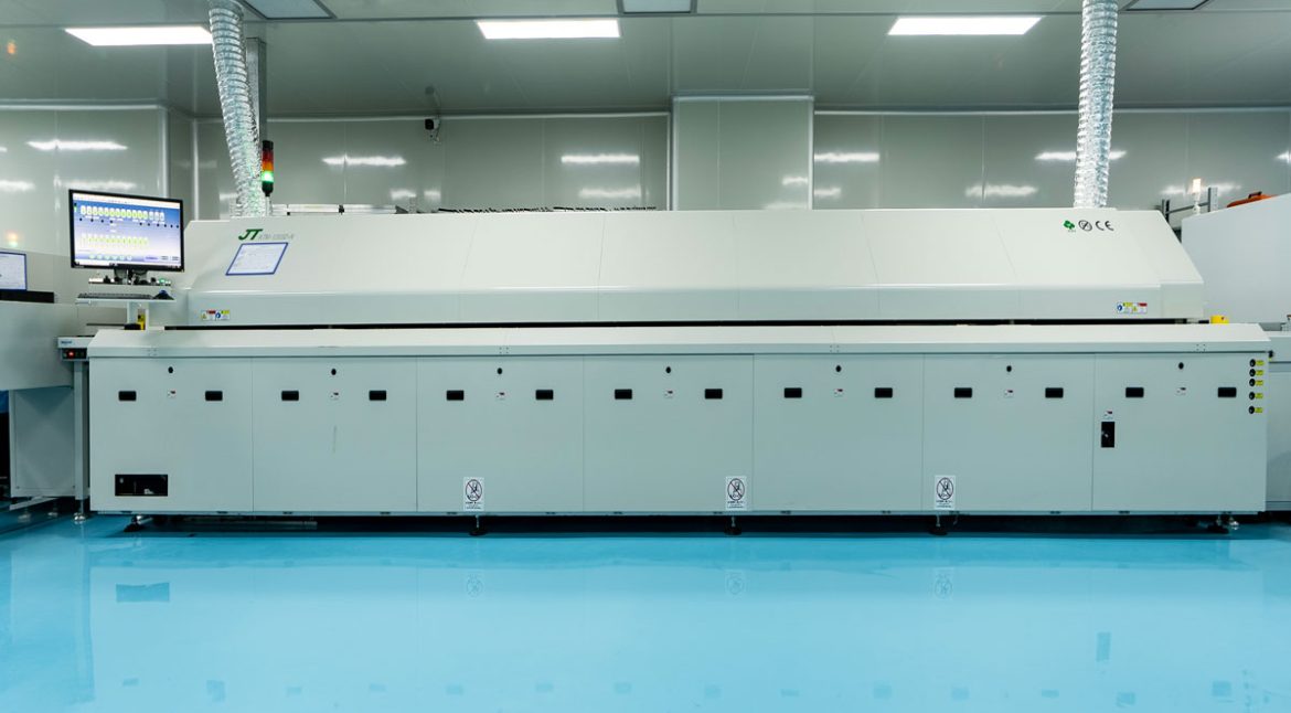
The reflow profile for a rigid-flex assembly has to be developed for the materials in it. The ramp rate, the soak and the peak are assessed against the board material, the solder paste and the largest and smallest components, and the flexible substrate is more sensitive to a fast ramp than a rigid one.
A ramp that is too fast increases warpage, and a board that warps during reflow does not hold the coplanarity that the fine pitch joints need. Uneven heating across the panel gives uneven wetting, which appears as a joint that formed on one side of a package and not on the other. The profile is therefore tuned from the state of the first article, as our SMT assembly process does for every new board, rather than copied from an earlier product that happened to share the paste.
Inspection and Fault Attribution
After reflow, an automatic optical inspection covers placement offset, polarity, tombstoning, bridging and the joints that can be seen. The joints that cannot be seen, such as the pads under a QFN, are covered according to the customer drawing, the acceptance criteria and an assessment of the risk in the particular design.
The more valuable part of the inspection is attributing a defect correctly. The same visible symptom can come from the paste deposit, the placement position, an incoming component, the carrier support or the reflow heating, and each of those has a different corrective action. A team that changes the wrong parameter makes the process less stable rather than more.
Some wearable products also require programming and functional checks such as standby current and interface communication. Those tests are defined by the customer: the program file, the programming interface, the supply range, the test steps and the acceptance criteria all have to be supplied, and they are executed against the drawing and the standard rather than against an assumed specification. Where the build includes a validated construction, the records that tie the process to the product are kept by our quality management system, and the data package expectations for a new project are set out in our design review checklist.
FAQ
Can a rigid-flex assembly be run without a carrier? Occasionally, if the flexible area is small and supported by the panel. For a tail that is free, a carrier is the difference between a repeatable process and an unstable one.
Why is the paste deposit checked before reflow? Because correcting it is a wipe and a reprint, while correcting the same defect after reflow means reworking a soldered joint.
What has to be supplied for programming and testing? The program file, the interface definition, the supply range, the test sequence and the pass criteria.