MOSFET Soldering and Temperature Rise on a 3D Printer Board
A 3D printer control board drives a heater, fans, motors and other outputs, so it carries several power transistors, driver devices, terminals and power components. If a load test shows that the device on one channel runs noticeably hotter than its neighbours, the first thing to establish is whether the difference can be reproduced. It may be caused by insufficient solder under the thermal pad, and it may equally be caused by a part that is not the specified type, by a drive signal that is wrong, by a load that has been set too high, by a missing heat path or by a test that ran for a different length of time.
Build a Comparison Before Touching the Board
Repairing, or any other rework, before the test conditions are fixed heats a device repeatedly without identifying anything. The board revision, the program revision, the supply voltage, the load, the running time, the ambient conditions and the position at which the temperature is measured are all recorded first. A second board of the same revision that behaves normally is then measured in the same fixture, on the same program and under the same load, which separates a single board problem from a condition that affects everything.
Thermal imaging is a good way to see the distribution of temperature across a board, but the reading is affected by the surface of the device, the angle and distance of the camera and the moment of the measurement. Keeping the procedure identical is what makes two images comparable, and the record should say which device was hot, when it became hot and whether the current was abnormal at the same time.
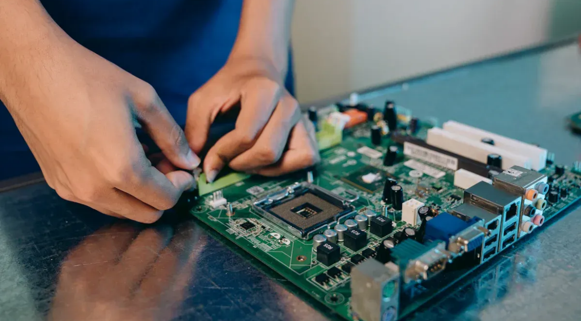
<img src="https://www.gopcba.com/wp-content/uploads/2020/12/service_04.jpg" alt="3D printer control board under thermal imaging” />
Controlling the Paste Under a Thermal Pad
A device with a heat spreading pad underneath cannot be treated as though the pad were an ordinary one. The stencil opening is evaluated from the pad structure, the package, the paste and the reflow conditions, and it is usually divided rather than made as one large opening. Too much paste lifts the body during reflow and leaves the perimeter joints uneven, while too little leaves the connection under the body weak.
After printing, the coverage, the volume and the offset are checked against the board. In the placement programme, the angle, the pick position, the landing point and the placement force are confirmed, because a device that lands well away from the centre of its pad will not form an even connection underneath however good the paste was.
The reflow profile has to accommodate the different thermal masses of the power devices, the small passives and the connectors on the same board. A profile that was used for a different control board is a starting point at best, and it is evaluated against the current board and the customer requirement rather than copied.
Separating the Solder, the Part and the Drive
If a single channel on a single board is hot, the joints, the position and the marking of the device at that reference designator are examined first. If the same channel is hot on many boards, the circuit revision, the part number in the bill of materials, the drive behaviour in the program and the test load all come into question.
Two power transistors in the same package are not equivalent in on resistance, in the ability to carry heat out of the package or in the voltage they will withstand. Where a substitute has been introduced, the customer confirms the full part number and the conditions it is approved for, and the thermal behaviour is not assumed to match because the package does.
The output of the driver and the control state are also confirmed against the test conditions the customer supplied. A device that has not been fully enhanced dissipates more than one that has, and the answer lies in the circuit and the code together rather than on the board alone, so the design data and the acceptance criteria are used instead of changing logic on the customer”s behalf.

When the Joint Is Hidden
Optical inspection covers the position of the device, the missing parts, the offset and the joints around the perimeter, and it cannot see the pad underneath. Where the load, the program, the part number and the external heat path have all been excluded, a further examination of the hidden connection is evaluated against the customer requirement rather than assumed.
The original temperature data and the reference designator are saved before any repair. After the device is replaced, the same load and the same running time are used again, and the case is only closed when the temperature rise, the current and the functional state have all returned to where they should be. If the temperature does not change after the repair, the repetition of the same replacement should stop and the investigation return to the drive, the load, the heat path in the board and the measurement method.
Validating a Process Change on a Small Batch
When a process adjustment has been identified, a small number of boards is used to validate it rather than changing the parameters for the whole batch. The print condition, the soldering result, the temperature distribution and the functional data are compared before and after, which shows whether the change is stable or whether it happened to work once.
A printer control board also has motor interfaces, fan outputs, temperature sensing and communication, so the functional test needs to state which of them are covered. Checking only that the board powers up leaves the outputs that the product actually depends on unverified. Our SMT assembly line covers the MOSFET soldering and the thermal pad work, the PCBA testing group runs the functional test under a defined load, and the results are retained under quality management.
What Has to Be Recorded
`r`n
The value of a thermal investigation comes from the record it leaves. The board revision, the program revision, the supply, the load, the fixture, the ambient temperature, the measurement position and the time at which the reading was taken belong together, and so do the images.
`r`n
When a device is replaced, the reference designator, the original part number, the replacement and the data before and after are kept, because a channel that behaves correctly with a different device is evidence about the device, not necessarily about the process. If the same position fails across several batches, the material lot and the incoming inspection come into the picture, and the record is what makes that comparison possible rather than a matter of recollection.
`r`n
Boards that were set aside and then returned to the line carry their repair state into the delivery record, so that the customer knows which units were touched and what was done to them. For a control board that drives a heater, that information is part of the safety case as well as of the quality file, and it is a good reason to record it rather than to leave it on the bench.
FAQ
Does a hot device always mean a bad joint? No. The part number, the drive signal, the load and the heat path all have to be excluded first.
Why compare against another board? Because it separates a board that is genuinely outside the norm from a test condition that makes every board look wrong.
What closes the case? The same load and running time producing the same temperature, current and function as a known good board.