



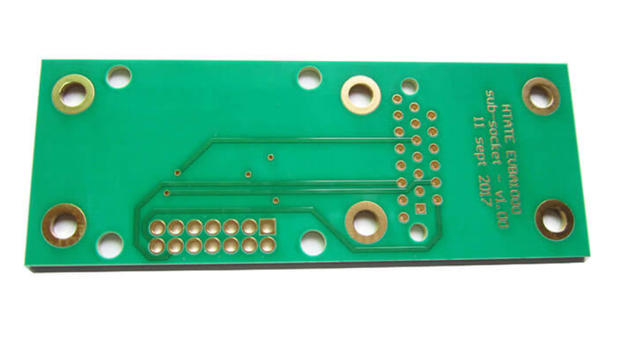
The 3W Rule: Trace Spacing for Crosstalk Control
Crosstalk is the least visible of the signal integrity problems and the one that designers most often try to solve with a rule of thumb. The 3W rule is the best known of those rules: keep the centre-to-centre spacing between two traces at least three times the trace width, and most of the electric field between them will fail to interfere. It is a good rule, but it is a rule with conditions, and applying it mechanically produces either wasted routing space or unexpected failures.
What the Rule Actually Limits
Two adjacent traces form a capacitor and a pair of coupled inductors. When one trace switches, the field that escapes it couples into the other, injecting a narrow spike at the victim”s input and, for long parallel runs, producing backward crosstalk that travels along the victim toward its source. The magnitude of that coupling falls as the traces move apart, and the 3W spacing reduces the mutual coupling by roughly seventy percent compared with traces that run side by side at minimum spacing.
Ten times the width is far more effective, reducing coupling by close to ninety-eight percent. That is a useful number because it frames crosstalk as a continuum. There is no threshold at which coupling switches off; there is only a series of spacings at which it becomes small enough for a particular design.

The Rule Depends on the Stack
The condition behind the 3W rule is easy to forget. Coupling between traces depends not only on their lateral separation but on how close they are to the reference plane beneath them. Two traces that sit close to a plane are strongly coupled to that plane, and the field between them is correspondingly weak. Two traces that float far above a plane couple strongly to each other instead.
On a four-layer board, where a trace might sit 5 to 10 mil above its reference plane, 3W is generally sufficient. On a two-layer board where the same trace is 45 to 55 mil above the reference, 3W may not be enough for a fast signal, because the traces are weakly tied to the plane and strongly tied to each other. The rule as normally stated assumes a 50 ohm transmission line environment, which is another way of saying it assumes a controlled dielectric height.
This is why the stackup decision constrains the routing rules and not the other way round. A design whose layer arrangement is described in this article on layer stackup design has already determined how much crosstalk a given spacing will produce.
Where 3W Is Required and Where It Is Not
Applying 3W to every net on the board would consume routing space that the design cannot spare, and it would deliver no benefit for the quiet majority of signals. The rule is meant for nets that are long, fast, or sensitive. Clock lines, differential pairs, video and audio signals, reset lines and other timing-critical nets belong in that group.
Where the routing is too dense to satisfy 3W everywhere, the sensible compromise is to apply it selectively to the sensitive nets and let the rest route at normal spacing. A design that gives the clock its 3W and lets a slow status line run closer to its neighbour is a design that has allocated its constraint budget where it matters.
It is also worth distinguishing between parallel runs and crossings. Two traces that cross at right angles couple over an area of almost nothing, and no special spacing is required. The problem is created by long, parallel, closely spaced runs, especially runs where the aggressor and the victim share a long distance at a constant separation.
Edge Rate Matters More Than Frequency
Designers often reason about crosstalk in terms of clock frequency, and that is the wrong variable. Coupling is driven by the edge rate, not the repetition rate. A 1 MHz signal with a 300 ps edge has a spectrum that extends far beyond 1 MHz, and it will couple into a neighbour as effectively as a much faster clock with a slow edge. The relevant bandwidth is set by the transition time, not the period.
This has a practical consequence for component selection. A device with a slower edge rate, or with a series resistor that slows the edge, produces less crosstalk for the same layout, and sometimes a small series resistor is a cheaper fix than a routing change. The coupling behaviour of the board as a whole is described further in this discussion of EMI suppression design principles, since crosstalk and radiated emissions share the same physical origin.
<img src="https://www.gopcba.com/wp-content/uploads/2026/09/55-1.jpg" alt="guard trace with ground vias between two sensitive signal traces” />
Guarding, Referencing and Layer Choices
A guard trace is a trace connected to ground and run between the aggressor and the victim. It works, but only if it is stitched to the reference plane at intervals along its length. An unstitched guard trace is a floating conductor, and a floating conductor couples energy from the aggressor and reradiates it into the victim, which can make the situation worse than no guard at all. Ground vias at both ends and along the run are what turn the guard into a shield.
Routing on adjacent layers is the other common oversight. Two traces on adjacent signal layers that run parallel couple vertically, and the coupling can be as strong as the lateral coupling the 3W rule is intended to control. Where two signal layers are adjacent in the stack, the designer should either avoid long parallel runs on them or cross the traces at an angle so that the parallel length is short.
Finally, the return path matters. A trace that crosses a plane split has a return current that detours, and the resulting loop couples into neighbours far more effectively than the trace alone would. The geometry of that return path is the subject of this article on high frequency traces and data buses.
Putting a Number on It
A designer who needs more than a rule of thumb should estimate the mutual capacitance and inductance for the actual geometry and compute the coupled voltage against the victim”s noise margin. In most projects that analysis is unnecessary, because the answer is dominated by a handful of decisions: how far the traces are above their plane, how long they run in parallel, how fast the aggressor edge is, and whether the victim is sensitive.
The practical workflow is to identify the sensitive nets first, classify them by edge rate and length, and then apply spacing rules to the classes rather than to the board. The result is a layout that satisfies 3W where it matters and still fits.
FAQ
Is the 3W rule measured edge to edge or centre to centre? Centre to centre. The spacing is three times the trace width measured from the middle of one trace to the middle of the next, which for typical widths gives a gap of about two trace widths between the copper edges.
Why does the 3W rule fail on a two-layer board? Because the traces sit far above the reference plane, so a larger share of their field couples to each other rather than to the plane. The same spacing that controls crosstalk on a thin four-layer stack can be insufficient when the dielectric height is ten times larger.
Does a guard trace always reduce crosstalk? Only when it is grounded and stitched to the reference plane at short intervals. A guard trace that is not connected to ground, or connected only at one end, behaves as a floating radiator and can increase the coupling it was meant to reduce.


2 Comments
Serpentine Routing for Length Matching
[…] The coupling between adjacent sections is the same mechanism that causes crosstalk between unrelated nets, and the spacing criteria are described in more detail in this article on the 3W rule for crosstalk control. […]
Eye Diagram Explained: Jitter, Noise and BER Margin
[…] Simulation is the tool that closes that loop before fabrication. A channel model built from the actual stackup can predict the eye for a proposed routing change, and the predicted result can be checked against a measured coupon afterwards. If the prediction and the measurement disagree, the model is missing a mechanism, and that discrepancy is usually more informative than the raw margin. The stackup and layer arrangement that set the channel loss are described in multilayer PCB advantages for high-speed designs. Practical routing rules that improve the measured result are collected in high-frequency trace and data bus routing, and the coupling mechanisms that degrade it are described in the 3W crosstalk rule. […]