
POFV Process in PCB Fabrication: Plated Over Filled Via
Fine-pitch ball grid array packages and stacked microvia structures have made one question unavoidable in HDI fabrication: what happens to the via after it is filled? If the via is left open, the pad above it is not flat and the solder joint that forms there is unreliable. If it is filled but not plated, the fill material is exposed to the assembly process and to the chemistry of later steps. The POFV process answers that question by filling the via with a paste and then plating copper over the filled via, so the finished surface is a continuous copper pad.
What POFV Means
POFV stands for plated over filled via, and the name describes the sequence rather than the structure. A via is drilled and metallized, filled with a conductive or non-conductive paste, planarized so that the surface is level with the surrounding copper, and then plated so that a layer of copper covers both the fill and the pad. The result is a via that is electrically and mechanically continuous with the pad above it, with no dimple and no exposed polymer. The alternative structures, an open via or a via that is filled but left unplated, each have a place, and comparing the three clarifies what POFV is for; the differences are set out in this article on via in pad versus plated through.
Process Flow
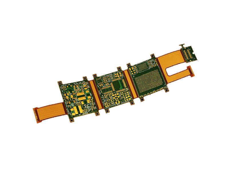
The sequence begins with material preparation. Panel stock is cut to the production size, and the holes defined by the engineering data are drilled at their nominal positions, using mechanical drilling for through holes and laser drilling for the microvias in an HDI build. Electroless copper follows, depositing a thin conductive layer on the insulating hole wall so that the subsequent electroplating step has a continuous seed to work from. Pattern transfer then defines the circuitry, and electroplating builds the copper on the exposed tracks and hole walls to the required thickness. The plating resist is stripped, and the filled via is created by plugging the hole with a paste and curing it. Planarization removes the excess material so the surface is level, and copper plating over the filled via completes the structure. Solder mask, surface finish and electrical test follow as in any other board.
Fill Material and Planarity
The fill has to do several jobs at once. It must not shrink away from the via wall during cure, it must survive the thermal excursions of assembly without cracking or outgassing, and it must not introduce a coefficient of thermal expansion that pulls the pad away from the laminate. Conductive and non-conductive pastes are both used, and the choice depends on whether the via also has to carry current or act as a thermal path. Planarity is the measurable outcome: after planarization the fill should sit within a small tolerance of the surrounding copper, with any remaining dimple kept to a value the assembly process can tolerate. For via-in-pad structures that value is often stated in the single-digit to low-tens of micrometres, and the acceptance limit should be written into the fabrication drawing rather than left to the shop.
Plating Over the Fill
Plating over the filled via caps the structure and rebuilds a continuous copper surface. The plating thickness must be adequate to carry the current that the pad will see and to survive the mechanical stress of planarization and assembly, and it must be uniform across the panel so that the pad height does not vary between the centre and the edge. Two failure modes are specific to this step. The first is a void or a thin spot where the fill surface is not perfectly clean, which creates a discontinuity under the plated cap. The second is over-plating around the via, which raises the pad above the surrounding surface and creates a step that interferes with paste release. Both are process control problems as much as design problems, and both are detectable by cross-section.

Where the Structure Is Used
The main driver is via-in-pad. Placing a via directly in the land of a fine-pitch BGA frees routing channels and shortens the connection, but it leaves a hole where the paste must be deposited. Closing that hole with a filled and plated structure restores a flat pad, and the same treatment is applied to a blind via that terminates on an inner pad and to stacked microvias, where one via lands directly on the previous one and the intermediate pad has to be solid. Boards that use the structure typically combine several build-up layers, which is the reason this technique is discussed together with other interconnected via formats in this article on electroplating and via filling in HDI.
Design Rules That Make It Work
The layout has to give the process room. The via diameter, the pad diameter and the annular ring must all be within the shop’s filling capability, because a via that is too large will not fill reliably and a via that is too small will trap air. Filled vias should not be placed so close to each other that the paste bridges between them, and the keep-out around the filled area should be respected by nearby copper features. A solder mask opening should be defined only where the pad is intended to be soldered, with a defined mask dam between adjacent pads so that the mask does not drift onto the land. Where vias are stacked, the layer-to-layer registration tolerance of the build-up process becomes the governing rule, and this is one of the reasons stacked structures are considered together in this article on blind and buried via stack selection.
Inspection and Common Defects
Because the critical features are internal, inspection relies on a combination of methods. Cross-sectioning confirms fill quality, plating thickness and dimple depth on a sample basis. X-ray inspection shows voids and misregistration in production volumes. Thermal cycling of a test coupon exposes fill materials that crack or delaminate after repeated excursions, which is the defect that appears after the board has shipped rather than before. Electrical test confirms continuity but says nothing about the mechanical integrity of the fill, so it should never be the only check on a structure of this kind.
Cost and Process Selection
POFV adds process steps, and every added step is an added cost and an added opportunity for yield loss. It is justified when the routing density or the package pitch leaves no alternative, or when the electrical performance of the short via-in-pad connection is worth the price. Where a design can place the via beside the pad instead of inside it, the simpler structure is cheaper and easier to inspect. The decision should be made during stackup planning, because it fixes the number of build-up layers and the drilling and filling capability that the fabricator must have.
FAQ
Is a filled via the same as a plated over filled via? No. Filling closes the hole, while plating over the fill adds a copper cap that restores a continuous flat surface and protects the fill material.
Why not simply leave the via open under a BGA pad? An open via draws solder away from the joint during reflow, leaving a void under the ball and an unreliable connection.
How flat does the finished pad need to be? Flat enough that the paste deposits evenly and the ball sits on a continuous surface, which in practice means holding the dimple within a small tolerance stated in the fabrication drawing.