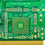
PCB Layout Design: Grid, Placement and Spacing Rules
Routing gets the attention, but most of a board’s electrical and manufacturing problems are decided before the first trace is drawn. A PCB layout design that begins with placement and finishes with routing costs less to complete, is easier to inspect, and behaves better at high frequency than one where the parts were scattered first and the traces were asked to compensate afterwards.
Grid and the Placement Order
The grid setting is the first practical decision, because it determines how neatly the board can be assembled and how easily the placement can be edited. A coarse grid of 50 to 100 mil suits large packages such as processors, memory and connectors, while a 25 mil grid suits resistors, capacitors and inductors. The point of a coarse grid is not speed; it is that parts snap into alignment with each other, pads line up in rows, and the assembly house sees a regular pattern instead of an arbitrary one.
Work in a fixed order. Place the mechanically constrained parts first: connectors, mounting holes, buttons, antennas and anything with a defined height. Then place the large active devices, and only then the passives. Doing it the other way round means re-placing the passives every time a connector moves.
Group by Signal Flow, Not by Convenience
The layout should follow the signal path through the circuit. Arrange functional blocks in the order the signal travels so that nets run in one general direction rather than doubling back across the board. This single habit shortens the average net, reduces the number of layer changes, and makes the return paths predictable. A block diagram drawn on paper before placement usually saves an hour of moving parts afterwards.
Keep each functional block compact and keep its local parts together. A regulator’s inductor, output capacitor and feedback divider belong beside the regulator, not spread across the board because there was space elsewhere.
Spacing Rules and Edge Clearance
component placement is governed by a few simple numbers. Leave at least 1 mm between the pad patterns of unrelated components so the placement nozzle and the rework tool have room to operate. Keep parts at least 2 mm from the board edge, because the router, the conveyor and the depanel operation all need clearance, and because a component near the edge is the first thing to break when the panel is snapped. Keep the arrangement parallel or perpendicular; a tidy pattern is not only cosmetic, it makes the assembly program faster and the inspection easier.
edge clearance is also an electrical parameter. Copper and components close to a routed edge sit near a discontinuity in the reference plane, and an edge-coupled line behaves differently when it is 0.2 mm from the cut instead of 1 mm. If the design has controlled-impedance traces running near the outline, give them more room than the mechanical minimum.
Board Shape and Aspect Ratio
A rectangular outline with an aspect ratio of about 3:2 or 4:3 is the easiest to panelise and the least likely to warp. Above roughly 200 mm by 150 mm, mechanical stiffness becomes a layout concern: the board will flex during reflow and during handling, so thicker material or stiffeners may be needed, and the fabricator should be asked before the outline is frozen.
High Frequency and Sensitive Blocks
Sensitive blocks need isolation before they need anything else. Place the crystal and its load capacitors as close to the oscillator pins as the footprint allows, keep the loop small, and do not route anything switching underneath. Keep switching regulators, clock buffers and high-current loops away from analogue front ends, sensor inputs and RF sections, and use the placement itself as the first line of shielding rather than relying on a can that may not fit.
Where an analogue and a digital block must meet, place the converter at the boundary and let the quiet side keep its own local ground pour, tied to the main plane at one point. Placement order and pad positioning covers how the pad geometry interacts with these decisions.
Thermal Layout
Heat sources should be spread out rather than clustered. Two regulators running at 80 degrees next to each other will derate each other, and a temperature-sensitive part placed between them will drift. Keep electrolytic capacitors and crystals away from hot inductors, give power devices a copper area to spread into, and plan the thermal vias at placement time rather than discovering the need during routing.
Power and Ground Before Signal
Decoupling capacitors belong on the same side of the board as the pins they serve, as close to the pin as the escape allows, with a short, wide connection to a via pair. Place them during the placement stage, not afterwards, because a capacitor that has to be fitted around a routed net is no longer decoupling anything. Assign the power and ground planes before routing starts; Ground routing and power trace planning explains how the plane structure constrains what the router can do.
Layout Checks Before Routing
Before the router starts, run a short review. Confirm that every part has a courtyard, that no courtyards overlap, that polarity and pin 1 markers are visible, that the edge clearance rule is satisfied, and that the assembly house can actually place the parts in the order the program assumes. It is cheaper to move a part on screen than to explain a shorted assembly. PCB design guidelines for manufacturability provide a checklist that covers most of these points.
FAQ
Placement for Assembly and Test
Placement decides how the board is built, so the assembly process deserves a pass of its own. Check the courtyard of every footprint against the real body size, not the nominal one; connectors and switches are frequently wider than the drawing suggests. Confirm that no two courtyards overlap and that the pick-and-place nozzle has room to descend vertically onto each part. Parts that stand close to a tall neighbour can be shadowed during reflow, and a component placed in the shadow of a connector will have a cold joint that only shows up in thermal cycling.
Leave probe access for the nets that will need to be measured. Test points on the power rails, the reset line and the programming interface save time on every unit, and a 1 mm pad costs nothing in area terms. Silkscreen reference designators should be legible after assembly, not hidden under the part, and polarity marks should be visible from the direction the operator actually looks. These details do not affect the schematic, but they decide whether the first build is a diagnosis session or a formality.
Should all components go on one side? Yes unless there is no alternative. A single-sided placement needs one reflow pass and one stencil, which reduces cost and removes the risk of parts falling off during the second pass. Only low-profile, low-mass parts should be considered for the second side.
How much does grid choice really matter? It matters for consistency rather than for electrical performance. A shared grid keeps pads aligned, makes the placement file predictable and lets the assembly program run faster, and it makes later edits far less disruptive.
Where should the crystal be placed? As close as possible to the oscillator pins, with the load capacitors beside it and a solid ground beneath. Keep switching nodes and high-current loops away from it, and do not route signals between the crystal and the chip.