Special Processes in PCB Prototyping: Impedance, HDI and Hard Gold
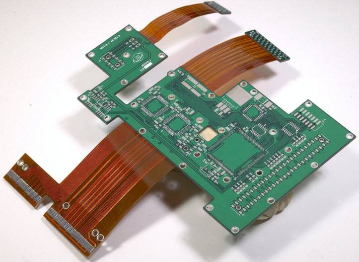
Most prototype boards are built with a standard process: drilled, plated, etched and finished. Some designs need more. Impedance-controlled nets, laser-drilled microvias, heavy copper layers and selective finishes all sit outside the basic flow, and each one changes what the fabricator has to do. Understanding those special processes early keeps PCB prototyping predictable rather than experimental.
Impedance Control and What It Requires
Impedance control is the most common special requirement. When a digital signal travels along a trace whose characteristic impedance does not match the source and the load, energy reflects, the edge slows and the receiver sees ringing instead of a clean transition. The fix is to define a target impedance, usually 50 ohm for single-ended nets and 85 to 100 ohm for differential pairs, and to design the trace geometry so it meets that target on the real stackup.
What makes it a special process is verification. The fabricator calculates the geometry from the dielectric thickness and copper thickness that actually exist after lamination, then places test coupons on the panel that can be measured with time-domain reflectometry. Prototype panels often need slightly different geometry to reach the same impedance, because resin content and press cycle differ from the volume build.
Blind and Buried Vias
Holes that do not pass through the whole board change the layer budget. A blind via starts on an outer layer and ends on an inner one; a buried via connects two inner layers and is invisible from outside. Using them frees the space that through holes would occupy on every layer, which allows higher routing density without adding layers, and shortens the stub that would otherwise distort a high-speed signal.
The manufacturing consequence is sequential lamination: the inner core is drilled and plated first, then laminated with the outer layers, and the remaining holes are drilled afterwards. Each additional lamination cycle adds cost and yield risk, so blind and buried via stack selection should be justified by the routing problem it solves rather than adopted as a default.
Copper weight is the second axis of special processing, and it interacts with everything above.
Heavy Copper and Thick Copper Boards
Copper foil of 2 oz per square foot and above is classified as heavy copper. The thick layer carries high current with a modest temperature rise, withstands repeated thermal cycling and improves heat spreading into the plane. It also makes trace width and current calculation easier, because doubling the copper thickness roughly halves the width needed for the same current and temperature rise.
The penalty appears at the etching stage. Thick copper etches laterally as well as vertically, so the achievable minimum line width and spacing are larger than on a 1 oz layer. Designs that combine heavy copper with fine-pitch components should use the heavy layer as a plane or as wide bus traces, and keep the fine routing on separately imaged thin layers.
Special Stackup Structures
Stackup is one of the most effective tools for controlling electromagnetic compatibility, and prototyping is where unusual structures are tried. A design with many signal nets, high component density and high clock frequencies benefits from multiple ground planes, tight power and ground plane pairs, and signal layers sandwiched between reference planes. Symmetry matters as much as layer count: an unbalanced stackup warps during assembly and makes yield unpredictable.
When a special stackup is used, the fabrication drawing has to describe it completely, including material types, dielectric thicknesses, copper weights and which layers carry controlled impedance. Vague stackup notes are the most common reason a prototype arrives with the wrong impedance.
Hard Gold, Gold Fingers and Nickel Palladium Gold
Gold finishes are requested for two different reasons, and the two are not interchangeable. Electroplated hard gold, normally with a nickel underlayer, is used on edge connectors and gold fingers because it resists wear from repeated insertion. It is an electrolytic process, so the fingers must be electrically connected during plating, which is why they are usually shorted together on the panel and isolated afterwards.
Electroless nickel electroless palladium immersion gold is a chemical process and needs no plating bus. The palladium layer acts as a diffusion barrier between the nickel and the very thin gold layer, which preserves solderability and wire bondability over a long storage period. The gold is only tens of nanometres thick, so the finish is flat and suited to fine-pitch assembly rather than to mechanical wear.

Mechanical features belong in the same conversation, because they change the drill and rout program as much as any plating step.
Countersunk and Depth-Controlled Holes
Countersunk holes are machined partway through the board with a larger diameter so that a flat-head screw sits flush with the surface. They are cut with a flat-bottom cutter, and the transition between the large and small diameters is a flat shoulder parallel to the board surface rather than a taper. Depth control is critical: too deep and the remaining laminate is too thin to hold the screw, too shallow and the screw head protrudes. Countersunk holes also need clearance below the shoulder, so the copper and components around them have to be placed with the machining operation in mind.
Depth-controlled holes need a special note on the fabrication drawing with the drill depth and tolerance stated, and they are usually placed away from dense routing so the machining does not disturb nearby copper. The PCB design guidelines for manufacturability that apply elsewhere on the board apply here as well, and keep-out rings around machined features avoid both electrical and mechanical surprises.
Choosing Which Special Processes to Use
Each special process adds cost, lead time and a new failure mode, so the starting point is always the smallest set that satisfies the design. Impedance control is required as soon as rise times are short or traces are long. Blind and buried vias are required when routing density cannot be met on a through-hole stackup. Heavy copper is required when current or heat demands it. Gold finishes are required when the connector is inserted repeatedly or when storage life matters.
A useful rule is to ask for each special process only where a requirement can be written down for it. Ordering a prototype is also a chance to validate the process itself. Ask for the impedance coupon results, the microsection of a filled via and the plating thickness report, then compare them with the specification. A prototype that meets its electrical targets but cannot be reproduced at volume is not a successful prototype.
FAQ
Is impedance control worth it on a small prototype? If the board has any net with a rise time under about 500 ps, or a trace longer than a quarter of the rise-time distance, yes. The cost is a small premium on fabrication and the discipline of defining the stackup before routing.
What is the difference between hard gold and immersion gold? Hard gold is a thick electroplated layer for wear resistance on connectors. Immersion gold is a very thin chemical finish for solderability. Substituting one for the other changes both the process and the function.
Can heavy copper and fine-pitch components share a board? Yes, if the heavy copper is confined to planes and wide traces on separate layers. Etching thick copper and fine lines on the same layer forces the fabricator to choose between them.