SMT vs Through-Hole Components for PCB Assembly
Every board carries a mix of surface-mount and through-hole parts, and the split is usually decided by habit rather than by analysis. Both families are mature, and the right choice depends on which property matters most for that net: density, thermal path, mechanical robustness or inspection access. This comparison sets out the practical differences between SMT and through-hole components so the decision can be made deliberately at the design stage.
Two component families, one board
Surface-mount devices are soldered to pads on the board surface, with no lead passing through the substrate. Through-hole parts have leads that pass through drilled holes and are soldered on the opposite side. The distinction matters because the assembly process, the inspection method and the mechanical load path are all different. Surface-mount assembly dominates modern production for the simple reason that it automates well, but through-hole parts have not disappeared, and selecting the wrong family for a critical function creates a problem that no amount of process tuning will fix. The comparison is not about one family replacing the other. A board built entirely from through-hole parts will be larger, heavier and harder to automate, while a board with no through-hole parts at all often struggles to accept a connector or a power device that must be mechanically anchored. Comparing SMT vs through-hole components is therefore a decision about process and function rather than about fashion, and it is best made net by net. The sections below cover the properties that genuinely differ in practice, so that the choice can be justified rather than assumed.
Size, component weight and board area
The density advantage of surface mount is substantial. A chip resistor or capacitor occupies roughly one tenth of the volume of its through-hole equivalent, and because the parts mount on the surface, the same function can be placed on a smaller board. Boards built with SMT parts commonly shed 60 to 80 percent of their original weight and 40 to 60 percent of their volume compared with an equivalent through-hole design, and component weight itself falls to around a tenth. On portable products those numbers decide whether the enclosure closes. The trade-off is that surface-mount pads and parts are small enough that handling, placement accuracy and solder paste volume become critical process variables.
Solder joint defect rate and inspectability
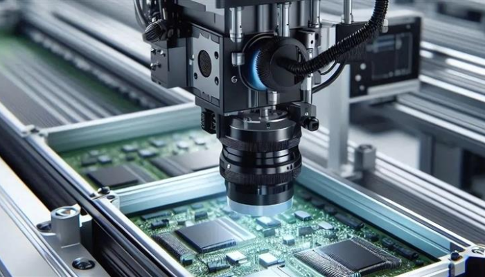
Surface-mount joints form a fillet between the pad and the termination and are made in a single reflow pass, which produces a low solder joint defect rate at high volume and suits automated optical inspection. Through-hole joints are formed individually, whether by wave, selective or hand soldering, and each one can be inspected visually from the solder side, which makes fault finding straightforward. That ease of inspection is a real advantage on boards with a low component count or on equipment that will be repaired in the field, where a technician needs to see and rework a joint directly.
High-frequency behaviour and interference
Short, flat connections are better electrically. A surface-mount part connects to the trace with almost no lead length, so parasitic inductance and capacitance are low and high-frequency performance is predictable. A through-hole lead adds a stub with its own inductance, which degrades performance as frequency rises and can act as a small antenna. For the same reason, circuits built with surface-mount parts generally produce less electromagnetic and radio-frequency interference, and they are easier to keep within an emission budget. Where a through-hole part is unavoidable in a fast circuit, keep its lead length as short as the assembly method allows.

Thermal performance
Power dissipation is where through-hole parts retain a genuine advantage. A lead that passes through the board conducts heat into the barrel, into the internal copper and out to the opposite side, giving a large thermal path in a small footprint. A surface-mount part relies on the pad area and on thermal vias beneath it to move heat into the planes. For a linear regulator, a power resistor or a device dissipating more than a watt or two, a through-hole package with a metal tab or a thick lead frame can be easier to cool than a small surface-mount package. If the design must stay surface-mount, the thermal performance has to be designed in with copper area and via arrays.
Vibration resistance and mechanical stability
Mass and attachment geometry decide how a joint behaves under shock and vibration. A surface-mount part is held by two or more small fillets and has little mass, so the load per joint is low; a large surface-mount capacitor can still crack at its terminations if the board flexes. A through-hole lead is mechanically anchored through the substrate, which resists shear and pull-out well and has historically given through-hole assemblies a reputation for vibration resistance. In extreme environments the deciding factor is often the mounting of the board rather than the component family, but a heavy part should never rely on solder alone; add adhesive or a mechanical retainer.
Choosing per function
The workable rule is to default to surface mount and make a deliberate exception where a property demands it. Keep connectors, high-power devices, large magnetics and parts that will be handled during field service in through-hole packages, and place everything else as surface mount. Then design the process around the exceptions: a mixed-technology board needs enough separation between through-hole and surface-mount parts so the second soldering step does not disturb the first, and the placement order and pad positioning should reflect which parts are reflowed and which are soldered later. Component mass also influences reflow behaviour, since a heavy part can float or shift as the paste liquefies, which is a common cause of component shift during reflow. The finish on the pad and lead must suit the alloy chosen, and the lead-free versus leaded solder decision applies to both families. gopcb reviews the component split with the customer because it determines the assembly route, the stencil design and the inspection plan.
Cost follows the same logic. Surface-mount assembly is cheaper per joint because it is automated, so a board that can be built predominantly with surface-mount parts will cost less to assemble even when the parts themselves cost the same. The exception is a low-volume or hand-built product, where a through-hole design avoids stencil and reflow setup entirely. Match the choice to the volume, not to a preference for one technology.
FAQ
Why do surface-mount parts reduce weight and size so much? A surface-mount part has no lead frame and no through-hole footprint, so its volume is roughly a tenth of the equivalent through-hole part. Across a whole assembly that typically removes 60 to 80 percent of the weight and 40 to 60 percent of the volume.
Are through-hole joints more reliable? The joint is mechanically anchored through the board, so it resists shear and pull-out well, and it is easy to inspect visually. That does not mean surface-mount joints are unreliable; a correctly designed surface-mount joint has a very low defect rate in volume production.
Which family is better for a high-power part? Through-hole packages usually win because the lead conducts heat into the board and out the far side. A surface-mount alternative can work if the layout provides enough copper area and thermal vias beneath the pad.