
Backplane and Modular Structures in Industrial Control PCB Design
An industrial controller can be built as one large board or as a set of smaller boards that plug into a common backplane, and the choice between backplane and modular structures is usually made early, because it determines the mechanical design, the connector strategy and the test approach. Both arrangements are in production today, and the decision is not a matter of one being more advanced than the other. It depends on how the product will be configured, serviced and extended over its life.
Two Ways to Build a Controller
The single-board approach places the whole controller on one printed circuit board. The alternative divides the controller into functions and gives each function its own board, with a common interconnection structure that carries signals and power between them. In the second arrangement the individual boards slide into guides and mate with connectors on a backplane, forming what is usually described as a card cage. Each arrangement has a different cost structure and a different failure mode, and the difference becomes visible only when the product has to be upgraded or repaired in the field.
The Large Single-Board Approach
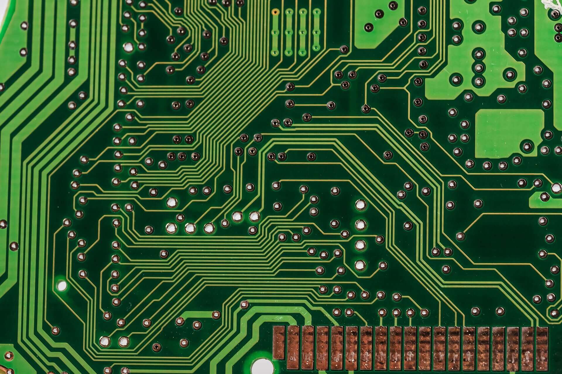
A large board can be organised around a main circuit board carrying the control core, the position control circuits, the operator interfaces and the system inputs and outputs, with additional small boards plugged into slots on that main board. The core typically contains the processor, memory and the timing and interrupt logic, with the program stored in non-volatile memory and the working data held in memory that is protected against power loss. The slots accept function boards such as a display controller, an interface board, a motor control board or a memory expansion board. The advantage of this arrangement is that the high-speed connections between the core and the function boards are short and can be defined tightly, and the whole assembly is compact. The disadvantage is that a fault in the main board removes the whole controller, and that the number of expansion positions is fixed at design time.
The Functional Module Approach
The modular approach divides the controller by function, with each function built as a board of the same size and the control software divided along the same lines. Because every module has the same mechanical outline and the same connector interface, the system can be configured by fitting the modules the application requires, and a module can be replaced without disturbing the rest of the rack. The interface between modules is a formal one, documented as part of the product rather than as an internal detail, which is what allows modules to be developed in parallel and replaced individually. The cost is paid in the interconnection: every signal between functions now leaves one board, crosses a connector, travels along a backplane and enters another connector, and each of those transitions has to be designed.
Choosing Between Them
The decision usually follows from four questions. How many different configurations does the product need? If the answer is many, modularity pays for itself in inventory and configuration effort. How long does the product have to stay in service, and how likely are the requirements to change? A modular rack can be extended by adding a card, while a large board requires a new revision. How quickly must a failed unit be restored? A plug-in card can be exchanged in minutes, while a board-level repair means removing the controller from service. Finally, how much does the interconnection cost? Where the interfaces are slow and few, the backplane is cheap; where they are fast and numerous, the backplane can dominate the design effort.
The System Bus and Its Loads
The system bus is the interconnection that all modules share, and it behaves differently from a point-to-point connection. Every module connected to the bus presents a load, and every connector and every stub between the bus and the module adds a discontinuity that reflects energy. As modules are added, the loading increases and the reflections accumulate, which is why a bus that works with two cards may fail with six. The countermeasures are to keep the stub from the bus to each module as short as the mechanical design allows, to terminate the bus correctly at the ends, and to define the connector pinout so that each signal is accompanied by a nearby return. Where the bus is fast, the choice between a simple parallel bus and a point-to-point switched fabric becomes a system decision rather than a layout decision. The return structure that makes the bus behave predictably is described in this article on ground routing and power trace planning.
Power Distribution Across the Backplane
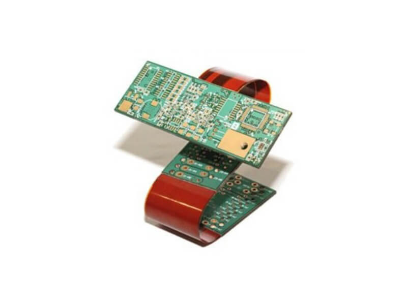
Power distribution deserves more attention in a rack than on a single board, because the current has to pass through connectors and along a backplane whose cross-section is limited by the mechanical envelope. Each rail has to be sized for the total load of all fitted modules, not for a typical configuration, and the voltage drop should be calculated from the connector to the furthest module rather than assumed to be negligible. The backplane copper is usually heavy, and the connectors must be rated for the current per pin as well as for the number of mating cycles. Where modules can be inserted while the system is powered, the inrush current and the sequencing of the supply rails become part of the design, and the mechanical keying must prevent a module from being inserted into an incompatible slot. The techniques used to carry large currents in copper are described in this article on trace width and current calculation.
Connectors, Keying and the Card Cage
The mechanical design of the rack determines how well the electrical design performs. Card guides position each module so that its connector aligns with the backplane connector, and the insertion force has to be within what the front panel can transmit without flexing the board. Keying prevents a module from being fitted into the wrong slot, both mechanically and by connector coding, and it is a requirement in any system where modules of different functions share the same outline. Where the enclosure is used as an electromagnetic shield, the front panel and the card edges need a continuous contact to the chassis, and that contact is part of the electromagnetic design rather than a mechanical afterthought.
Serviceability and Fault Isolation
The strongest argument for a modular structure is often service rather than configuration. When a controller is divided by function, a failure can be isolated to a module by swapping it, and the repair can be done by a technician rather than by an engineer. This changes the test strategy as well: each module can be tested on its own before it is fitted, and the assembled rack can be tested as a system, which gives two levels at which a fault can be found. A single-board design has fewer interfaces to test but no way to divide the diagnosis, which usually results in a longer repair time in the field.
Layout and Stackup Decisions
Both approaches end in the same set of layout problems, but with different emphases. The backplane is usually a thick board with heavy copper for its power rails and enough layers to route the bus with a continuous return; the stackup is chosen for those two requirements, and the options are described in this article on layer stackup from one to eight layers. The function modules are denser and benefit from the prototype-oriented rules for a first build, described in this article on multilayer PCB prototype requirements. In both cases, the interface definitions should be frozen before the boards are routed, because a change to a connector pinout is a change to every board in the system at once.
FAQ
Is a modular structure always better than a single board? No. Modularity buys configurability and serviceability, and it costs connector and backplane complexity. Where the configuration is fixed and the interfaces are fast, a single board is often the better engineering choice.
Why does a system bus fail only after several cards are fitted? Because each card adds capacitive loading and each connector adds a reflection. The accumulated effect can cross the threshold even though no individual addition looked significant.
What should be frozen first in a rack design? The interface definition: connector type and pinout, keying, module outline and the power rails each slot provides. Everything else follows from it.