Electroless Copper in PCB Holes: Process Steps and Control
Every plated through hole in a printed circuit board starts life as an insulating wall. The resin left by the drill does not conduct, and electroplating cannot begin on a surface with nowhere for the current to flow. Electroless copper is the step that solves that problem: a chemical process that deposits a thin conductive layer over the entire panel, including the inside of every hole, so that the electrolytic plating which follows has something to build on.
What Electroless Copper Has to Achieve
The requirement is deceptively simple. The deposit has to be continuous, adherent, and thick enough to carry the plating current into the hole, which means a fraction of a micron on the hole wall and a similar layer on the surface copper. It has to cover every hole in the panel, including the smallest, and it has to do so without contaminating the chemistry that follows.
A hole that is not fully covered will plate only partially, and the result is an intermittent connection that passes continuity testing at low current and fails in the field.
Desmear: Removing the Resin Smear
Drilling generates heat, and heat melts the resin. The melted resin is smeared across the hole wall by the drill, covering the copper edges of the inner layers. If the smear is not removed, the plating will sit on resin rather than on copper, and the connection between the barrel and the inner layer will not exist.
desmear is the removal of that layer. For epoxy laminates the standard approach is a permanganate-based chemistry, often preceded by a solvent swell that softens the resin so the permanganate can attack it. For polyimide and other high-temperature materials, a plasma step is normally used instead, because the resin resists the wet chemistry.
Etchback and the Connection to the Inner Layer
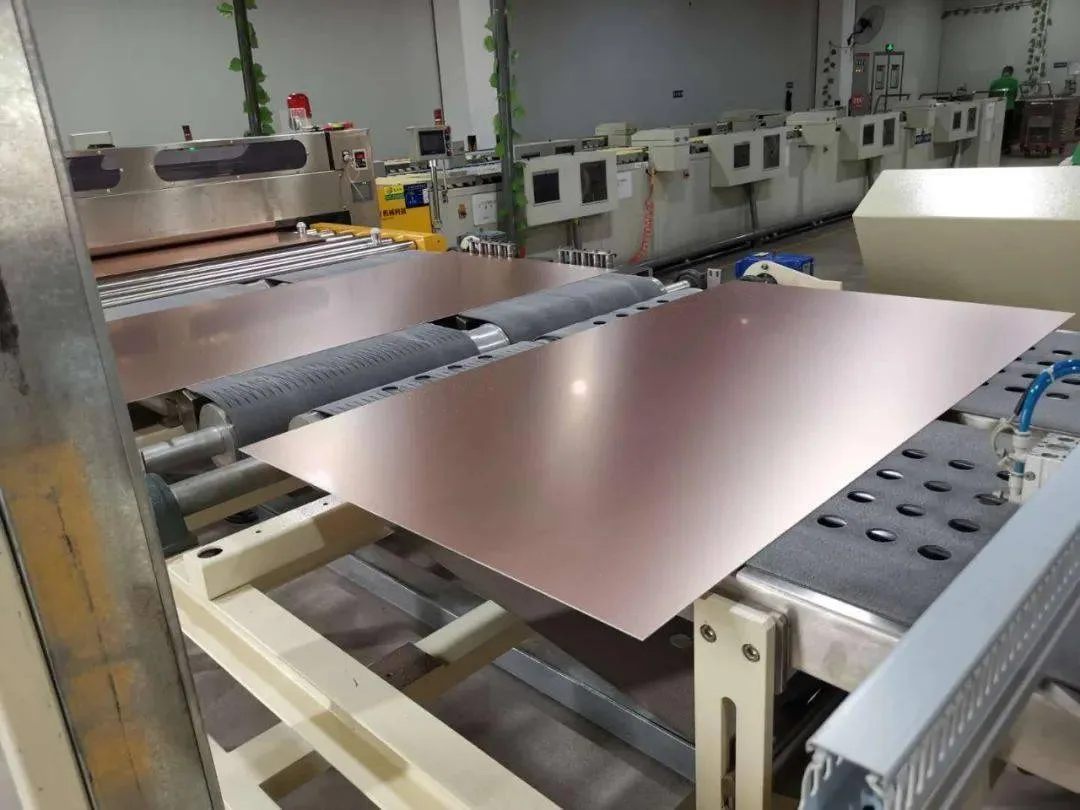
Where a more reliable connection is required, the desmear is extended into an etchback: a controlled removal of resin so that the copper of the inner layers protrudes slightly into the hole. The plated barrel then wraps around that protruding copper rather than butting against it, which increases the contact area and makes the joint more tolerant of thermal cycling.
Too much etchback is as harmful as too little. Excessive resin removal leaves the dielectric between layers unsupported and can create a void around the inner layer connection, which is a defect that shows up in microsection as a gap rather than as a bond.
Conditioning and Activation
Before a catalyst can be applied, the hole wall has to be conditioned. The conditioning step adjusts the surface charge so that the catalyst particles, which are usually palladium-based, will attach to the dielectric rather than stay suspended in the solution. Without it the catalyst coverage is patchy, and the electroless deposit follows that pattern.
Activation then deposits the catalyst itself, and a subsequent acceleration step exposes the active metal so that the copper can deposit on it. Each of these stages has its own concentration, temperature and dwell time, and each has a range outside which the process fails in a way that is difficult to see until the panel is sectioned.
The Electroless Bath Itself
The bath contains a copper source, a complexing agent that keeps the copper in solution, a reducing agent that supplies the electrons, and stabilisers that prevent the reaction from running away. The process is autocatalytic: once copper has deposited, it catalyses further deposition, which is why the bath has to be carefully stabilised and why its chemistry changes as it is used.
Copper concentration, temperature, pH and the loading of the bath all affect the deposition rate, and the plating rate has to be matched to the dwell time. A bath that deposits too slowly leaves a thin, discontinuous layer; one that deposits too fast tends to produce a rough, poorly adherent deposit that can break up during the electrolytic step.
Coverage in High Aspect Ratio Holes
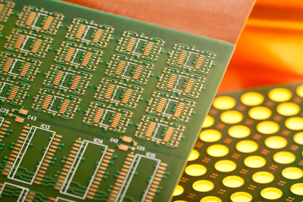
The most demanding requirement is coverage inside small, deep holes. The chemistry has to exchange through the hole, which is limited by diffusion, so the deposit becomes thinner towards the middle of the barrel. Beyond an aspect ratio of about 8 to 1, this becomes a real constraint, and the process has to be supported with agitation, panel movement or vibration.
Where the design needs holes above that ratio, the fix is usually in the process parameters and the equipment rather than in the chemistry. The relevant figure for the designer is the fabricator’s maximum aspect ratio for a given hole size. Copper plating defects and their prevention covers how poor coverage shows up in the finished board.
The Transition to Electrolytic Plating
The electroless layer is a seed, not the finished barrel. Once the panel has a conductive coating, it can be clamped and electroplated, and the electrolytic step builds the copper up to the thickness the design requires, typically 20 to 25 micrometres in the barrel for a general-purpose board.
The quality of the electrolytic deposit depends on the quality of the seed. A thin or discontinuous electroless layer produces a barrel with voids or with a nodular, brittle structure, and no amount of electrolytic plating will repair it. Electroplating additives in PCB production explains how the electrolyte and its additives control the grain structure of the copper that follows.
Control Parameters and Their Symptoms
Water Quality Is Part of the Process
Every stage of the sequence ends with a rinse, and the quality of that water is a process parameter rather than a utility. Contaminants carried from one tank to the next change the chemistry of the bath that follows, and ionic residue left on the hole wall interferes with the catalyst. Conductivity and pH of the rinse water should be monitored, and the rinse should be long enough to remove the previous stage’s chemistry completely.
The same applies to the handling between stages. Panel surfaces that are touched, or that sit wet in air for too long, oxidise or pick up contamination, and the resulting defects appear as patchy plating rather than as a systematic failure, which makes them hard to diagnose after the fact.
Most electroless copper problems can be traced to a small set of variables. Insufficient desmear leaves a smear that shows up as a void between the barrel and the inner layer. A weak conditioner or a spent activator produces patchy coverage that appears as a missing or thin deposit. A bath outside its temperature or concentration window produces a deposit that plates quickly but adheres poorly.
The control method is the same in each case: measure the parameters rather than judging from the finished board, and section a sample regularly so that the hole wall can be inspected directly. Where the design uses microvias, the same principles apply with tighter tolerances and a different geometry. Electroplating and via filling in HDI describes the extension of this process to small blind holes.
FAQ
How thick is the electroless copper layer? Only a fraction of a micron in the hole. It is a seed layer whose purpose is to make the surface conductive, not to provide the finished barrel thickness.
Why is desmear necessary if the hole is clean? Drilling always leaves resin smear on the hole wall, even when the hole looks clean. The smear is invisible and electrically insulating, and it prevents the connection to the inner layers.
What limits the aspect ratio that can be plated? The rate at which the chemistry can exchange inside the hole. Beyond roughly 8 to 1, agitation and equipment are needed to keep the deposit continuous.