PCB Debugging a New Board: Tools, Flow and Soldering
A new board rarely works the first time it is powered, and the difference between a project that recovers in a day and one that loses a week is usually the debugging method rather than the fault. Bring-up on a fresh design is a discipline: solder a section, test it, solder the next, and keep a written record of what was measured.
Soldering as a Debugging Skill
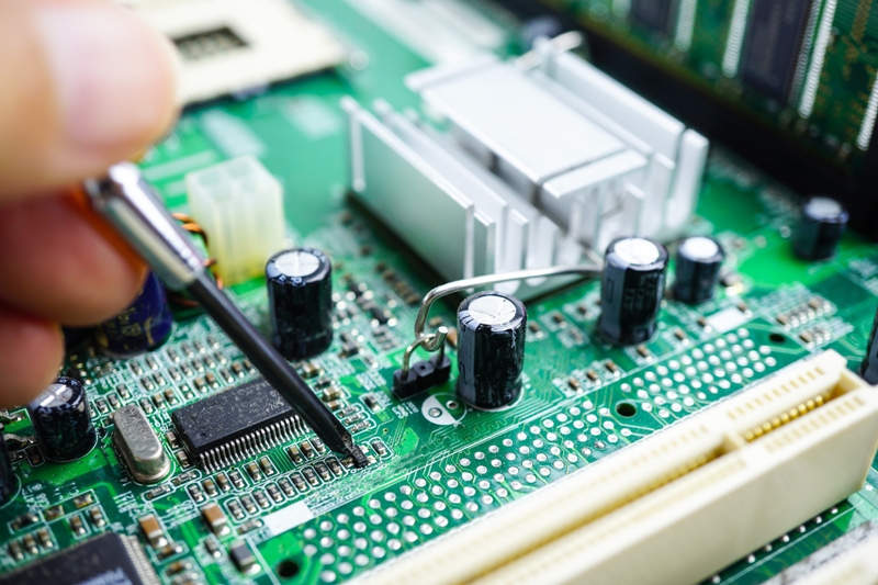
On a new design the parts cannot all be fitted at once. Each block has to be populated, powered and verified before the next is added, because a fault that appears after twenty components have been placed is much harder to localise than one that appears after two. That means the engineer doing the debugging is also doing the soldering, at least during bring-up.
The skill matters for a second reason: a poor joint is indistinguishable from a design fault until it is ruled out. A cold joint, a small solder bridge or a reversed component will produce exactly the symptoms of a design problem, and chasing a design fault that does not exist is the most expensive way to spend a day.
Adding One Function at a Time
The sequence should follow the power architecture. Verify the input protection and the first regulator with no load, then add the load and check the rail under current. Only when every rail is correct should the processor be populated, and only when the processor is running should the interfaces be added.
Resist the temptation to fit everything and see what happens. The information gained from a board that does not work at all is much less than the information gained from a board where the first three stages have been proven.
The Test Equipment That Matters
A multimeter is the first instrument and the most used. It measures continuity, resistance, voltage and current, and it works on an unpowered board, which is where the most useful checks happen: is this net actually isolated, is that joint actually made, does this rail measure what it should.
Resistance and continuity measurements are the foundation of bring-up work, and they are the only measurements that can be taken safely before the board is powered for the first time. Getting into the habit of measuring before energising is what keeps a mistake from turning into a destroyed board.
A bench power supply with a current limit is the second. Current limiting is what prevents a wiring mistake from destroying a component, and watching the current as the supply comes up tells you more about the state of the board than the voltage does. If the current climbs towards the limit before anything is enabled, stop and find out why.
Checking Before Powering
The first checks are all done with the board unpowered: verify that the supply inputs are not shorted to ground, that the rails are not shorted to each other, that polarity is correct at every connector and that no component is fitted the wrong way round. These checks take a few minutes and prevent the majority of the damage that occurs during bring-up.
A useful habit is to measure the resistance from each rail to ground and compare it with the value expected from the decoupling network. A reading far below the expectation means a short, and it is much cheaper to find now than after the smoke.
Bring-Up With Current Limit
Bring the supply up slowly with the current limit set to a modest value. If the board draws more than expected, turn it off immediately and investigate rather than raising the limit. Most failures at this stage are shorts, reversed parts or a device inserted with the wrong orientation.

Once the rails are correct, check the clock and the reset line before expecting any digital activity. A processor with no clock will draw current and do nothing, and its behaviour is easy to misread as a firmware problem.
Systematic Fault Finding
The efficient method is bisection. Divide the circuit into halves, determine which half contains the fault with a measurement, and repeat. Random probing wastes time and often introduces new problems; a measurement that halves the search space is worth ten that do not.
Where a signal is expected and absent, check the source before the destination. Where a signal is present but wrong, check the supply and the reference first, because a device operating outside its supply range produces behaviour that looks like a logic fault.
Instruments Beyond the Multimeter
An oscilloscope is what turns a symptom into an observation. It shows whether a clock is present and clean, whether a bus is toggling, and whether a supply is sagging when a load switches on. Most intermittent faults on a new board are visible on a scope before they are understood.
A signal generator and a programmable load cover the remaining cases, where the board has to be exercised with something other than its own firmware. Together with the multimeter and the supply, they are the four instruments a bring-up bench needs.
Recording the Result
Intermittent Faults and How to Trap Them
An intermittent fault is the hardest case because it disappears when it is observed. The usual causes are a marginal solder joint, a connector that makes contact only in some positions, a component that drifts with temperature, or a timing margin that is exceeded only at an extreme. Each suggests a different way of provoking the fault.
Freeze spray and a hot air tool are the standard tools for the thermal case: cool a region and see whether the fault appears or disappears, then narrow the region. For the mechanical case, flex the board gently and probe the suspect joints. For the timing case, the fault is usually visible on a scope as a marginal edge or a setup time that is only just satisfied, and the fix belongs in the layout or in the clock rather than in the firmware.
Whatever the cause, the fault should be reproduced deliberately before it is declared fixed. A board that stops misbehaving after an unexplained change has not been repaired, merely disturbed.
Write down what was measured and what was changed. Bring-up generates a list of modifications, and those modifications are the input to the next revision; a list that exists only in memory is a list that will be partly lost. Where a modification is a patch wire, record its position on the assembly drawing as well.
A test report that states what was verified, at what conditions and with what result turns a successful bring-up into evidence that the design works. PCB design quality characteristics covers the wider set of evidence worth keeping, and Low cost signal quality improvements lists the changes that most often rescue a marginal design. Multilayer PCB prototype requirements covers the test access that makes bring-up easier to plan for.
FAQ
Should the whole board be populated before testing? No, except for very simple designs. Populate and verify one block at a time so that a fault can be attributed to a known change.
Why use a current-limited supply? Because it turns a destructive fault into a measurable one. The board either draws the expected current or it does not, and the answer arrives before any component is damaged.
What should be checked before applying power? Rail-to-ground resistance, rail-to-rail isolation, connector polarity and component orientation. These four checks catch most of the damage-causing mistakes.