




Rigid-Flex PCB Construction and Bend Radius Rules
A rigid-flex PCB replaces a stack of cables, connectors and separate boards with one continuous structure that folds into the enclosure. The rigid sections carry the components and the fine-pitch routing, while the flexible sections carry the connections and bend to reach around corners. The result is a lighter, more reliable assembly with fewer solder joints, provided the design respects the mechanical limits of the flexible material.
This article covers how the structure is built, how the layers are bonded, and the geometric rules that decide whether the finished part survives a million flex cycles or cracks in the first assembly.
What a Rigid-Flex PCB Is
The distinguishing feature is a single lamination that contains both rigid and flexible areas. The rigid areas are built up from multiple layers of FR-4 or a similar laminate with copper on each layer, exactly like an ordinary multilayer board. The flexible areas use a thin polyimide base with rolled or electrodeposited copper, and they remain bendable because the rigid material is removed from those zones.
The transition between the two is where the design is won or lost. At the boundary, the flexible core extends into the rigid section so that the plated through holes can pass through it and anchor it. That overlap region must be wide enough to carry the vias and to resist delamination, and no bend may be placed inside it. Protection of the exposed flex in service is a separate decision, and the conformal coating guidelines explain when a coating helps and when it stiffens a flex area more than the design can tolerate.

The Layer Structure and Materials
The flexible core is usually polyimide, chosen for its high glass transition temperature and its dimensional stability over temperature. The copper is either rolled annealed, which has large grains and tolerates repeated bending, or electrodeposited, which is cheaper and more suitable where the flex area is formed once and never moved again.
Rigid layers are conventional FR-4 or a low-loss material if the design carries high-speed signals. What matters is that the flexible and rigid dielectrics expand differently, so the stack has to be balanced about the neutral axis just as a rigid board is, with the flexible core placed so that the copper in the bend region is neither in tension nor in compression when the part is folded.
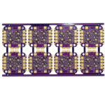
<img src="https://www.gopcba.com/wp-content/uploads/2026/08/2-3-jpg.webp" alt="Bend area of a flexible circuit with stiffener” />
Layer Bonding and Adhesive Systems
Two bonding systems dominate. Adhesive-based construction uses a bond ply or a coverlay with a thermoplastic or thermoset adhesive that flows during lamination. Adhesive-free construction bonds the coverlay directly to the polyimide surface, which gives a thinner finished part and better dimensional stability, at a higher material cost.
Layer bonding in the rigid area is conventional prepreg lamination, but the flexible area needs its own coverlay to protect the conductors. The coverlay openings must be sized to match the pad geometry, and the adhesive that flows into those openings has to be controlled, or it will creep onto the pads and interfere with soldering. Whenever the bend area also has to survive assembly, the coverlay thickness and the adhesive type are as important as the copper thickness.
Designing the Bend Radius
The rule that governs everything is the bend radius relative to the total thickness of the flexible section. For a design that is formed once during assembly and never moves again, a radius of roughly ten times the total flex thickness is a practical minimum. For a part that will flex repeatedly in service, the ratio rises to between 20 and 40, depending on the number of cycles required.
Copper is the limiting material, not the polyimide. Copper work hardens and cracks when it is repeatedly stretched, so the conductors in a dynamic bend area should run perpendicular to the bend line, and they should be as thin and as wide as the current allows. Placing conductors at 45 degrees to the bend line, or parallel to it, concentrates the strain on a single trace and shortens the life of the part.
Stiffeners and Support Areas
Flexible material is too thin to support a connector reliably, so stiffeners are bonded to the back of the flex where a connector, a switch or a heavy component is mounted. A stiffener is typically a piece of FR-4, polyimide or stainless steel, and its thickness is chosen so that the flex behaves like a rigid board locally while staying thin elsewhere.
The stiffener has to extend beyond the component footprint in every direction, and its edge should not coincide with a bend line, because a step change in stiffness concentrates stress. The flexible circuit outline design rules cover the board outline and the stiffener placement that keeps the assembly flat where it needs to be flat.
Manufacturing Sequence and Yield
Rigid-flex is built in more steps than a rigid board, and each one adds risk. The flexible core is imaged and covered, the rigid layers are laminated around it, the rigid areas are routed away to expose the flex, and only then are the through holes drilled and plated. Because the drilling happens after the flex is exposed, the panel has to be handled carefully throughout.
Yield is dominated by delamination at the rigid-to-flex transition and by the accuracy of the routing that defines the flex outline. Both are improved by generous overlap between the flexible core and the rigid section, and by avoiding sharp internal corners in the routed outline. The comparison of flexible board constructions is worth reading before committing to a rigid-flex stack, because a simpler flexible design sometimes meets the requirement at lower cost.
Applications and Where It Pays
Rigid-flex earns its cost where space is tight, where reliability matters, and where the alternative is a bundle of cables and connectors. Cameras and sensor modules, medical catheters, aerospace instrument panels and handheld instruments all take advantage of the fact that the interconnect is soldered once and never handled again.
The saving is not only in volume. Every connector removed is a contact that cannot corrode and a solder joint that cannot crack under vibration. When those costs are included, a rigid-flex PCB often competes with a conventional assembly even at moderate volumes, and it becomes clearly cheaper in any product that is expected to survive shock and thermal cycling.
FAQ
How many flex cycles can a rigid-flex PCB survive? A static flex that is folded once during assembly has no cycle requirement, and a radius of ten times the flex thickness is adequate. A dynamic flex that moves in service needs a radius of 20 to 40 times the thickness, and the achievable cycle count should be confirmed by test on the actual stack.
Can I place a via in the bend area? No. Vias are rigid points in a flexible region and concentrate stress at the barrel. Keep every via in the rigid sections or in a stiffened area, and route the flex area with conductors only, running perpendicular to the bend line. If the layout forces a via into the bend region, the geometry should be changed rather than the rule relaxed, because reworking a flex does not restore the fatigue life that was lost.
Is rigid-flex more expensive than a cable assembly? The board itself usually costs more, but the comparison should include the connectors, the cable, the assembly labour and the field failure rate. Once those are counted, rigid-flex is frequently the cheaper option, particularly where the assembly is small or must survive vibration.


1 Comment
Flexible PCB Coverlay: Materials and Openings
[…] the flex is part of a rigid-flex construction, the coverlay has to stop short of the rigid section and the transition must be planned so the film […]