Low-Cost PCB vs High-Quality PCB: What Differs
Every board order involves the same trade-off, and it is usually presented as a simple choice between cheap and good. That framing is unhelpful, because the difference between a low-cost PCB and a high-quality PCB is not a single feature but a set of decisions about material, copper, layer count, tolerance, and testing. Knowing which decisions matter for a given product is what turns the choice into an engineering judgement.
What a low-cost PCB looks like
Cost-reduced boards share a recognisable pattern. They are built on standard FR-4 laminate with commodity copper foil. The design keeps layer count low, uses wider traces and generous spacing, and avoids advanced features such as microvias or buried vias. Components are common, off-the-shelf parts. Testing is limited, often relying on visual inspection rather than a defined test programme.
Each of those decisions is legitimate on its own. The problem appears when several of them are made for the same product without anyone deciding that they were acceptable, because the effects accumulate rather than cancel.
Where a low-cost board is the right answer
For a prototype, a concept demonstrator, or an educational project, a cost-reduced board is often correct. The purpose is to learn whether the circuit works, and the fastest way to learn that is to build it and test it. Simplified processing also shortens turnaround, which matters during early iterations when the design is still changing.
Budget is the other honest reason. A startup validating an idea does not need a controlled-impedance stackup, and spending on one delays the decision that actually needs to be made.
What you give up
The compromises show up as reliability. A thinner copper layer is more easily damaged by heat, a lower-grade laminate delaminates sooner, and a wider minimum feature size limits how well the design can control impedance. Poor solderability and marginal joints appear on assemblies that were never intended to be tested.
Performance limits follow the same pattern. Boards of this class are a poor fit for high-frequency signals, for high-current power paths, and for anything mission critical. Their service life is also shorter, which becomes expensive when the product is not the board but the system that contains it.
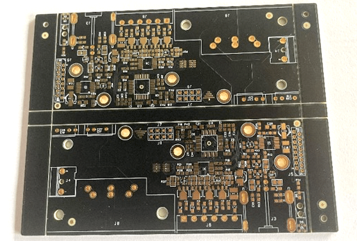
A cost-reduced board is a tool for learning, not a foundation for a product that has to survive a warranty period.
What a high-quality PCB includes
A quality board is defined by specification rather than by price. The laminate is chosen for the electrical and thermal requirement, the copper weight is set by the current, the surface finish is chosen for the assembly process and shelf life, and the stackup supports controlled impedance where a signal needs it. Where density demands it, the design uses HDI features such as microvias and buried vias.
Components are certified parts with traceable sources, and testing is a defined programme rather than a final glance. Automated optical inspection, X-ray inspection for hidden joints, and functional test each verify something the others cannot.
What that buys
The return on that specification is reliability, service life, and performance margin. A board that holds its impedance across the frequency range behaves predictably in a system, and one built with verified materials survives thermal cycling instead of failing at the first temperature excursion. Documentation and certification against recognised quality standards also matter commercially, because they are what allows a product to be sold into regulated markets.
The cost is visible immediately: a higher price per unit and, often, a longer lead time. The risk in the other direction is over-engineering, where a simple product is specified to a standard that adds cost without adding value.
Choosing for the project
Four questions settle most cases. Is this a prototype or a product? A board built to answer a technical question should be cheap and fast. Will the product be used in a mission-critical role, such as medical, aerospace, or automotive safety? That rules out every cost-reduction shortcut. Does the design depend on advanced features such as HDI, controlled impedance, or high layer count? Those features only hold their tolerance on a controlled process. And is the product heading for volume? Reliability problems become far more expensive once a fault is multiplied across thousands of units.
When the answers point in different directions, the decision belongs with the consequence of failure rather than with the price. A board that fails in a prototype costs a week; the same board failing in a shipped product costs a recall.
Balancing the two approaches
The choice is not binary. Design optimisation reduces complexity without reducing performance, and a hybrid approach applies high-grade material and tight tolerance only where the circuit needs them: the radio section, the power path, or the high-speed interface, with standard material elsewhere.
Staged sourcing is the other common pattern. Prototype with a cost-reduced board to prove the design, then move to a quality specification for production, keeping the layout and the panel identical so the change is a process change rather than a redesign. It helps to work with a manufacturer that offers both classes, since the same engineering review then carries across the transition.
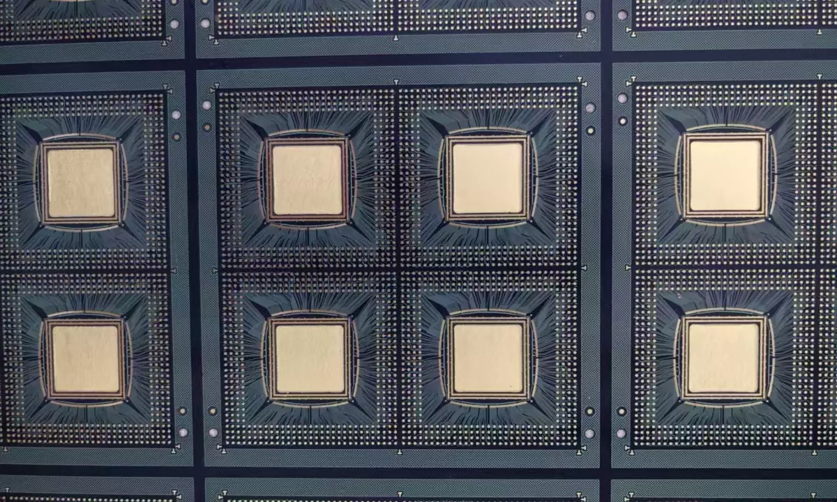
The transition from prototype to production is the point where a quality decision is made, whether or not anyone makes it deliberately.
The specification lines that matter
When two quotations differ, the difference is usually in a handful of lines. Copper weight determines how much current the traces can carry and how well the board survives thermal cycling. Impedance control determines whether a high-speed interface works on the first build. The laminate grade sets the glass transition temperature and therefore the reliability of the assembly process. The surface finish decides shelf life and solderability. Test coverage decides which defects are found before shipping.
Those five lines are the ones to compare, and each can be evidenced. A supplier that will not state them numerically is quoting a price rather than a product. The wider question of how much signal quality can be recovered without a premium is explored in low cost signal quality improvements, and the differences that survive into the manufacturing process are covered under copper plating defect prevention.
A rule of thumb
Spend on the parameters that the product cannot tolerate failing, and accept standard values everywhere else. Most boards have one or two critical nets, one thermal hotspot, and one interface that has to work on the first build, while the rest of the board is ordinary copper that does not care which grade of laminate carries it.
FAQ
Is a high-quality PCB always more reliable? Only when the specification matches the application. Material and tolerance that are correct for high-frequency work buy nothing on a slow, low-power design, while a cost-reduced board used in a harsh environment fails regardless of how carefully it was made.
Can I upgrade an existing design without re-layout? Usually yes. Moving to a better laminate, a heavier copper weight, or a different surface finish changes the process rather than the geometry, so the same fabrication data can be used at both levels.
How do I compare two quotations fairly? Ask both for the same specification lines in writing, plus the test coverage and the certification. Two prices that describe different products cannot be compared, and the lower one is often lower for a stated reason. Our guide to multilayer prototype requirements lists the parameters worth pinning down before ordering.