Automotive PCB Requirements: Materials, Layers and Qualification
Automotive electronics is the most demanding mainstream application for printed circuit boards. A board that fails in a phone is an inconvenience, while the same failure in a braking or steering system is a safety event. That difference explains why automotive PCB requirements reach well beyond what an ordinary industrial board must satisfy, and why the cost structure behind them looks different too.
What Makes Automotive Different
The operating environment is the first factor. Temperature swings from a cold start to a hot soak under the bonnet can exceed a hundred degrees, and the board sees that cycle thousands of times over its life. Vibration, humidity, salt spray and chemical exposure are all present, and none of them can be designed around by changing the enclosure.
The second factor is consequence. A defect that would be a warranty claim elsewhere becomes a recall, so the acceptance criteria, the test coverage and the documentation trail are all stricter. IPC Class 3 is the usual performance target, and it changes how a defect is judged rather than merely how much inspection is performed.
Board Type and Layer Count
A simple body control function may fit on a double-sided board, but anything involving a processor, a network interface or a power stage moves to four layers at minimum. Engine control units, driver assistance modules and battery management systems typically use six to twelve layers, because they combine high-speed differential pairs, high-current supply rails and sensitive analogue measurement on one substrate.
The layer count is set by three requirements rather than by routing convenience: a continuous reference plane under every critical signal, separate planes for the supply domains, and enough routing capacity to avoid long parallel runs between switching and sensing nets. Each of those adds a layer that is justified by performance rather than by density.
Base Materials
Standard FR-4 covers most of the board, and high glass transition grades are chosen where the assembly and operating temperatures demand better dimensional stability. Polyimide is used in the hottest locations, particularly near the engine and in transmission control, because it holds its mechanical and electrical properties far beyond the epoxy limit.
Metal-backed substrates appear where a power stage has to shed heat into the housing, and high-frequency laminates appear where a radar or a communication interface needs controlled loss. Electric vehicle power electronics use combinations of all three, which is one reason those boards carry the highest material cost in the vehicle.
Thickness, Copper and Thermal Design
Board thickness follows the mechanical requirement first and the electrical one second. A thicker board resists vibration and connector insertion force better, while a thinner one suits tight packaging. Copper weight is set by the current the board must carry, and heavy copper is common on power stages because it also spreads heat more effectively.
Thermal management is designed into the copper rather than added afterwards. Thermal via arrays under power devices, generous copper areas on both sides and a defined interface to the enclosure are the standard tools, and on a board with several heat sources the whole thermal field has to be considered together rather than device by device.
Surface Finish
Hot air solder levelling is the cheapest finish and remains usable where joints are coarse and the board is consumed quickly. Electroless nickel immersion gold is far more common in automotive work, because it gives a flat surface for fine-pitch and ball grid array parts and holds its solderability through the longer storage that automotive supply chains often involve.
Immersion silver fills the middle ground, offering good solderability and a flat surface at a lower cost than gold, though it needs care during handling because the surface is more sensitive to contamination. The finish should be specified per the assembly process rather than by habit, since the wrong choice shows up as intermittent solderability rather than as an obvious defect.

Design Complexity and Tolerance
Ordinary routing rules cover most of an automotive board, but the sensitive sections are tighter. High-density interconnect is used where component pitch and pin count force it, adding process steps and cost. Controlled impedance control is required for the communication buses and the radar front ends, which adds engineering and test coupons rather than only geometry.
Component selection and placement carry the same weight. Parts must be qualified to the automotive temperature grades, and their placement has to respect the thermal field, the mechanical load paths and the separations that keep a noisy switching node away from a millivolt-level sensor input.
Test, Qualification and Traceability
Automotive programmes are built around a documented quality system rather than around a final inspection. The manufacturing facility is expected to hold a recognised automotive quality certification, and the process is expected to be capable and monitored rather than merely inspected.
Test coverage follows the risk. Automated optical inspection covers the visible joints, X-ray covers the hidden ones, flying probe or fixture test confirms electrical integrity, and functional test at temperature verifies behaviour under load. Material and process traceability from panel to finished unit is part of the deliverable, because a field investigation is impossible without it.
Cost Drivers and Hidden Charges
The visible cost follows the familiar pattern: material grade, layer count, copper weight, finish, tolerance and quantity. A conformal coating adds a further step where the board must survive condensation or chemical exposure, and it must be applied so that it does not trap contaminants under the coating.
The charges that surprise buyers are the ones outside the board price. Tooling and stencils, qualification testing, first-article documentation, packaging for moisture-sensitive parts and inbound freight all attach to the order, and expedited lead time can multiply the price. Requesting a complete delivered quotation rather than a bare board price is the simplest way to avoid the surprise.
Board Architecture in Practice
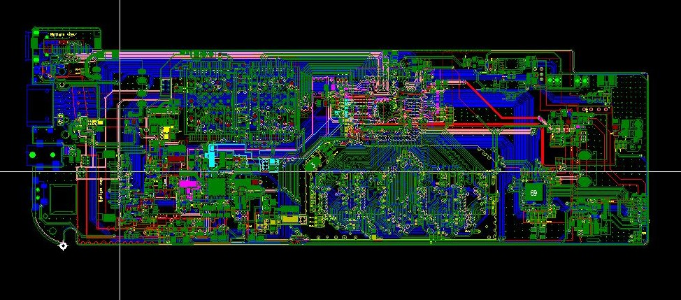
Most automotive boards end up partitioned. The power stage occupies one region with heavy copper and thermal vias, the digital section another with a continuous ground reference and controlled-impedance buses, and the sensor interface a third with its own quiet analogue ground. Mixing those regions in the same area is what produces noise problems that no component change can repair.
Connector placement drives the partitioning. Each harness interface should sit at the board edge nearest its function, so that the return current of a high-current load does not travel beneath a millivolt-level sensor trace on its way out of the board. That single rule resolves a large share of automotive layout problems before they occur.
Serviceability matters as well. Test points on the supply rails, a defined ground reference for probing and accessible communication lines all make dealer-level diagnostics possible, and they cost almost nothing when they are added during layout rather than after production has started.
FAQ
Is IPC Class 3 always required for automotive? Not for every board, but it is the common default for anything safety related. The distinction matters because Class 3 acceptance is stricter on the defects that affect reliability, not merely on how many defects are allowed.
When is polyimide justified? Where the operating temperature or the thermal cycling exceeds what a high glass transition epoxy can survive with margin. Near the engine and in transmission control, it is usually the only material that meets the reliability requirement.
How much does a faster lead time cost? Expedited service commonly adds a substantial premium over standard scheduling, and the figure rises sharply at very short turnarounds. Automotive volumes are usually planned far enough ahead that this is avoidable.