AR Device PCB: Design Challenges for Wearable Displays
An augmented reality headset is one of the hardest packaging problems in consumer electronics. Two displays have to be driven at high frame rate, several cameras have to be captured and processed, a radio has to work beside all of that, and everything has to fit into a frame that weighs less than a pair of glasses and runs from a small battery. An AR device PCB is a study in compromise.
What the Board Has to Support
The display path is the most demanding. Each eye has its own panel with its own timing controller, and both have to be driven with low latency and with the exact skew that the optics assume. A mismatch between the two eyes produces a visible artefact that no amount of processing can remove.
The sensor path adds several camera interfaces and an inertial measurement unit. The radio adds Wi-Fi, Bluetooth or both, with an antenna that has to work beside a metal frame and a battery. The power path converts a single cell to several rails while dissipating as little heat as possible in a device that touches the user face.
Mechanical Form Factor
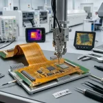
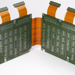
The board is designed to the frame, not the other way round. That usually results in a rigid-flex construction, with one or more rigid islands for the dense components and flexible sections that follow the arms and the bridge of the frame. The flexible sections carry the display links and the sensor links between the islands.
That construction removes connectors and saves thickness, but it imposes the constraints of a flex design: a minimum bend radius, no plated through holes in the bend region, and conductors placed near the neutral axis. A rigid-flex board for a headset is usually one of the most intricate parts in the product, and the stackup has to be agreed very early, as described in blind and buried via stack selection.
Power Density and Thermal Budget
Everything on the board is running at once and there is nowhere for the heat to go. The displays generate their own heat in the optics module, the processor generates heat where it is mounted, and the battery is intolerant of high temperature. The thermal budget is therefore small and shared.
The design response is to reduce dissipation rather than to move it. Low power interfaces are chosen over the fastest available, rails are sequenced so that unused sections are switched off, and the load is spread across the board so no single area becomes hot. Copper area and thermal vias then move what remains into the frame, and the low power techniques involved are the same as those used in ground routing and power trace planning.
High Speed Interfaces in a Small Space
The display links are short but fast, and short does not mean easy. A link that crosses a rigid-flex transition passes through a change of dielectric thickness and a change of geometry, which is an impedance discontinuity unless the transition is designed. The trace width has to be adjusted across the boundary to keep the impedance constant.
The camera links add several more high speed interfaces on the same small board. Keeping each one on its own layer pair, with a continuous reference plane and no parallel run beside another high speed net, is what keeps them from interfering. Crosstalk is the dominant risk because everything is close together, and the usual separation rules apply with less room to apply them.

Antenna and Radio Coexistence
A headset has at least one radio and often two, and both need antenna volume that competes with the displays and the battery. The antenna region has to be kept free of copper and of the metal frame, which in an AR product is genuinely difficult because the frame is usually metal for structural reasons.
Once the antenna is placed, the rest of the board has to be arranged so that the display and camera interfaces do not radiate into it. That means keeping the high speed nets away from the antenna region, filtering the supplies that feed the radio, and verifying the result in the assembled product rather than on a bare board, following the discipline described in conformal coating and board protection.
Rigid-Flex Transitions and Layer Planning
Every transition between a rigid island and a flexible section is an electrical and mechanical discontinuity, and the design has to treat it as one. Electrically, the dielectric thickness changes, so the trace geometry has to be adjusted to hold the impedance. Mechanically, the transition is where the coverlay ends and where the stiffener is bonded, and it is where delamination and cracking begin if the geometry is abrupt.
The layer plan therefore places the high speed links on the flexible layers that run continuously through the whole assembly, with the rigid layers added around them for the dense component areas. Keeping those links on one pair of layers throughout avoids layer changes at the transitions, which is worth more than any other single decision in an AR board.
Manufacturing and Yield
The rigid-flex construction, the fine pitch components and the sensor packages all reduce yield relative to an ordinary board. The design can help by giving the assembly process room: pad sizes above the minimum, adequate solder mask clearance, sensible fiducials and a panel arrangement that keeps the flexible sections supported during reflow.
Testability is the other half. A headset board cannot be probed easily once it is folded into a frame, so the test points and the fixture have to be designed into the flat state before folding. That means planning the test access during layout rather than adding it afterwards, and the same discipline applies to the assembly process described in lead-free versus leaded solder.
Software Interface and Bring-Up
Because the board has few accessible test points once assembled, most of the bring-up happens over a debug interface during development. That interface, and the firmware that exercises each block, should be defined before the first prototype so that the board can be validated in stages rather than only as a finished product.
A staged bring-up sequence, checking the supplies first, then the clocks, then the individual interfaces, turns a board that does not boot into a short list of candidates. On a product as integrated as a headset, that discipline is the difference between a two week debug and a two month one.
FAQ
Why is rigid-flex used instead of separate boards? Because the frame has no room for connectors and cables. A rigid-flex board follows the shape of the product, removes mating interfaces and reduces the assembly steps, at the cost of a more expensive and more constrained board.
How is heat removed from a sealed headset? Mainly by reducing dissipation and spreading what remains through copper and into the frame. There is no airflow, so the design has to assume that the heat leaves through the surface that touches the user.
Can off the shelf display links be used? They can, provided the impedance and skew requirements of the panel are respected through the rigid-flex transition. The link budget should be verified with a simulation that includes the transition geometry.