FR4 vs Mid-Loss Laminate: Dk, Df and Skew Compared
Standard FR4 is the default laminate for the overwhelming majority of circuit boards, and its limits only become visible as data rates rise. Between the ordinary grade and the expensive low loss materials there is a middle family of modified epoxy laminates, often described as mid-loss, that costs a fraction more and buys a meaningful improvement in loss and in stability.
Deciding whether that middle family is worth the premium is a comparison of three parameters: the dielectric constant, the dissipation factor and the behaviour of the material when a fast edge crosses it.
What the Two Materials Are
Standard FR4 is a woven glass fabric in an epoxy resin, with a glass transition temperature that depends on the grade and a dielectric constant between roughly 4.2 and 4.6 depending on the resin content and the test method. It is available from many suppliers, in many constructions, at a low price.
A mid-loss laminate uses a modified resin chemistry to reduce the polar groups that cause dielectric loss. The glass fabric is unchanged, so the mechanical behaviour is familiar, but the dissipation factor falls by a factor of two or three and the dielectric constant is slightly lower and more consistent between lots.
Dielectric Constant and Geometry
The dielectric constant sets the geometry for a target impedance. A lower value means a wider trace or a thinner dielectric for the same 50 ohms, which is convenient on a dense board because it relaxes the minimum line width and reduces conductor loss.
It also sets propagation delay. A lower dielectric constant means a faster signal, which shortens the electrical length of a route and changes how a length matching budget is calculated. When a design migrates from standard FR4 to a mid-loss grade, the delays shift and the matching has to be recalculated rather than scaled.
Dissipation Factor and Loss
The dissipation factor is the parameter that motivates the change. Standard FR4 sits around 0.015 to 0.02 at a gigahertz, while a mid-loss material typically falls between 0.008 and 0.012, and the low loss families continue below 0.005.
The effect on the channel is proportional to the length and to the frequency. On a short route, the difference between FR4 and a mid-loss grade may be a few tenths of a decibel, while on a long backplane channel it can be several decibels, which is the difference between a link that closes and one that does not.
Skew and the Glass Weave
Skew is the difference in propagation delay between the two conductors of a differential pair. Part of it comes from length mismatch, which the layout controls, and part comes from the glass weave. A trace that runs along a glass bundle sees a slightly different dielectric constant from one that runs between the bundles, and if the two halves of a pair sit over different parts of the weave, the delays differ.
A mid-loss laminate does not remove the effect by itself, because the glass is still there. What helps is a spread glass fabric, a lower dielectric constant that reduces the sensitivity, or routing the pair at an angle to the weave. Where the skew budget is tight, the material choice and the routing direction have to be considered together.
Thermal and Process Differences
Mid-loss materials are engineered to process like FR4, which is their main commercial advantage. Drilling, desmear, lamination and plating parameters usually need only minor adjustment, and the same fabricator can run both materials on the same line.
The differences that do appear are in the glass transition temperature and in the decomposition temperature, both of which tend to be higher in the modified grades. That is helpful for a board that sees multiple reflow cycles or a lead free assembly profile, but it changes the lamination cycle and should be confirmed rather than assumed.
Cost and Availability
The price premium over standard FR4 is modest, typically a fraction rather than a multiple, and it is far below the cost of the low loss materials. Availability is broad, although a specific construction may have a longer lead time than the standard grade.
The engineering cost of switching is also low, because the mechanical design rules are unchanged. That combination makes the mid-loss family the natural first step when a design begins to be loss limited, before considering a much more expensive material.
Where Each Material Fits
Standard FR4 remains appropriate for low speed digital, analog, power and control circuits, and for any short high speed route where the loss is a small part of the budget. It is also the right choice for the non critical layers of a mixed stackup.
A mid-loss laminate earns its place on longer high speed routes, on backplanes, on server and storage boards with several gigahertz of signalling and anywhere the loss budget is close to the limit. It is the pragmatic answer for a design that needs more margin but cannot justify the cost of a low loss material.
Mixed Stackups
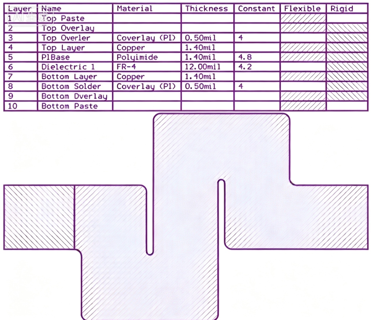
There is no requirement to use one material for the whole board. A common construction puts the mid-loss material on the layers carrying the highest speed signals and keeps standard FR4 on the power, ground and low speed signal layers. The stackup drawing then shows two material types, and the lamination sequence has to account for their different thermal behaviour.
Mixing materials is usually cheaper than making the whole board from the higher grade, and it is easier to process than a stack that combines epoxy with a much softer material. The important discipline is to state the layer assignment explicitly, because a fabricator who is forced to guess will optimise for availability.
Design Checklist
Start from the loss budget, not from the material catalogue. Calculate the loss of the longest channel with standard FR4, compare it with the available margin and use the difference to decide whether a mid-loss grade is required. Then check the skew budget separately, since it responds to different measures.
gopcb builds boards in standard FR4, mid-loss and low loss materials and can compare a stackup against a given channel budget, including the impedance and delay changes that follow from a material substitution.
One further caution applies to both materials: the numbers quoted in a datasheet are measured with a defined method, and two suppliers may report the same material differently. Where the loss budget is tight, the value that matters is the one measured on a coupon built in the intended stackup, and comparing datasheets from different sources is not a substitute for that measurement. Asking the fabricator for a coupon result before the design is frozen costs a small amount of time and removes a large part of the risk from the material decision.
FAQ
Is a mid-loss laminate worth the extra cost? On a long high speed channel, usually yes. On a short route where the loss is a small part of the budget, the improvement is difficult to measure and the standard grade is sufficient.
Does changing the material change the impedance? Yes. The dielectric constant changes, so the trace width or the dielectric thickness has to be recalculated to hold the same impedance rather than carried over from the previous stackup.
Can the two materials be mixed on one board? They can, and it is a common way to control cost. The layer assignment and the lamination cycle both have to be specified in the stackup drawing.
Related reading: high frequency laminate selection, high frequency trace routing, impedance discontinuity analysis, and multilayer PCB advantages.