MRI PCB Design: Low Noise, Channel Count and Reliability
Magnetic resonance imaging is one of the most demanding electronic environments in medical equipment. The magnet is always on, the gradient coils switch hundreds of amps in milliseconds, the radio frequency transmitter puts kilowatts into the bore, and the receiver is asked to detect a signal that may be a fraction of a microvolt. An MRI PCB sits inside that environment and has to keep the receive chain quiet through all of it.
Where the Boards Sit
A scanner contains several distinct electronic subsystems. The gradient amplifier and its control, the radio frequency transmit chain, the receive chain with its preamplifiers and digitisers, and the reconstruction computer with its data links all have their own boards and their own requirements.
Physically they are separated, because the transmit and receive functions cannot share a space without interfering. The receive electronics are usually in the magnet room, close to the coils, while the reconstruction hardware is outside the shielded room and connected by a fibre link.
The Receive Chain and Its Noise Floor
The signal received from a coil is small, and the signal to noise ratio of the image is decided largely in the first amplifier. The preamplifier is placed as close to the coil as possible, sometimes inside the coil housing itself, so that the cable does not add loss before the first stage of gain.
On the board, that means a very short path from the connector to the amplifier, a low noise supply and a ground reference that is not shared with any digital return. The design principles are the same as for any high impedance front end, set out in mixed signal PCB design guidelines, but the margin required is larger because the signal is smaller.
Channel Count and Routing Density
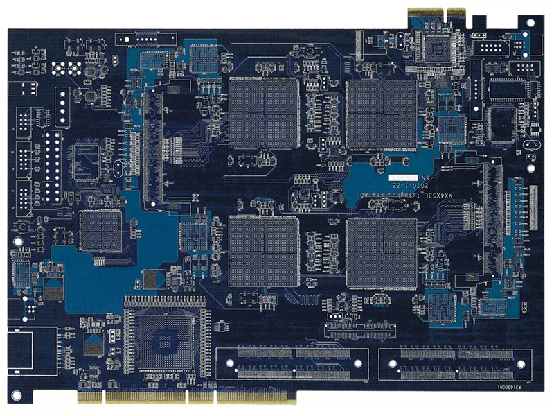
Modern scanners use arrays of many small coil elements, each with its own receive channel. The channel count drives the board layout, because every channel needs its own signal path, its own filtering and its own connection to a digitiser, and they all have to be kept separate from each other.
Crosstalk between channels degrades the parallel imaging performance, so the layout has to maintain isolation through spacing, grounded barriers between signal paths and separate returns. Where the channels are digitised on the board, the converters themselves must be synchronised without introducing jitter that differs between channels. Channel count is the main reason these boards use a high layer count with dedicated ground and power planes.

Interference from Gradients and Radio Frequency
The gradient coils create switching magnetic fields that induce voltages in any loop of conductor, and the radio frequency transmitter generates a strong field that couples into everything inside the bore. A board in that environment has to be designed so that the interference does not reach the sensitive nodes.
RF shielding, in the form of enclosures around the receive electronics, is the primary defence, and their effectiveness depends on the continuity of the enclosure and on how it is bonded to the board ground. The effectiveness of that RF shielding depends on the continuity of the enclosure and on how it is bonded to the board ground, and the general techniques for containing emissions are described in EMI suppression design principles.
Isolation and Patient Safety
Equipment that connects a patient to mains powered electronics has to provide isolation against fault currents, and the applicable standard defines the required withstand. In a scanner this applies to the physiological monitoring inputs, to the patient communication system and to any accessory that touches the patient.
The layout consequence is a defined isolation barrier with the required creepage and clearance, no conductor crossing it and no shared return. The barrier also has to survive the cleaning and disinfection that the equipment receives between patients, which makes the coating specification part of the safety requirement, as discussed in conformal coating and board protection.
Thermal Stability
The scanner room is air conditioned, but the electronics dissipate real power and the gradient coils heat the bore. Temperature changes shift the gain of the preamplifiers, the delay of the digitisers and the tuning of the coils, and all of those affect image quality.
Keeping the sensitive components on a common thermal island, and providing a thermal path to a cooled surface rather than relying on air, keeps the drift common and therefore compensatable. Calibration performed at the operating temperature, rather than at a room temperature bench, is what makes the compensation meaningful.
Materials and Construction
The receive boards are usually conventional multilayer constructions with controlled impedance on the signal layers and generous ground planes. Materials with stable dielectric properties are preferred where the receive path is long, and a low loss laminate helps where the signal travels any distance before digitisation.
Where the front end is inside the coil housing, the board also has to be non magnetic and compatible with the magnet environment. Any ferromagnetic material in the assembly is a hazard, so the component and fastener selection is checked explicitly rather than assumed from the data sheet.
Reliability and Serviceability
A scanner is expected to run for many years with scheduled maintenance and no unexpected downtime, and the boards are replaced as modules rather than repaired in place. That changes the design priorities: connectors must mate reliably through several replacement cycles, and the module must be testable outside the system.
Built in self test functions, accessible test points and an identification device that stores calibration data on the module all reduce the time a service engineer spends on site. Those features cost board area, and boards that omit them tend to cost more over the life of the product than the area was worth.
Test and Verification
Verification combines electrical measurement with imaging performance. Noise figure, channel gain and crosstalk are measured at board level, and the whole system is then evaluated on a phantom to confirm that the image quality meets the requirement.
Because the limits are set by the overall image, the board specification should state the allocation for the electronics rather than a general target. A receive chain that meets its own specification but has no margin left for the coil or the reconstruction path is not a solution, and the allocation is what prevents that situation from being discovered late. It should be recorded in the design description so that a later change to any subsystem can be assessed against the budget it was given, and a margin should be held back rather than spent on the first revision, because the coil and the reconstruction path will both change before the product ships.
FAQ
Why is the receive chain placed in the magnet room? To keep the cable short. Any cable between the coil and the first amplifier adds loss and noise before the signal is amplified, which directly reduces the signal to noise ratio of the image.
Can standard FR-4 be used? For many of the digital and control boards, yes. The receive path benefits from a stable, low loss material, and the choice follows from the length of the path and the noise budget.
How is crosstalk controlled between channels? By spacing, by a grounded barrier between paths and by separate returns for each channel. The converters also need a common, low jitter clock so that the channels stay aligned.