Rail Transit PCB: Vibration, Temperature and Long Life
Rolling stock electronics are specified for a service life measured in decades, in an environment that combines continuous vibration, wide temperature swings, humidity and an electrical supply that is anything but clean. A rail transit PCB therefore resembles an industrial board in its circuit but resembles aerospace hardware in the evidence it must produce.
Where These Boards Are Used
Trains and metro systems contain traction control electronics, signalling and interlocking equipment, passenger information systems, door controllers, brake control units and the communication systems that link them. Some of these sit inside the cab, others under the floor or on the roof where the environment is far harsher.
The distinction matters because the requirements differ. A board inside an air conditioned cab sees a modest environment, while one mounted on the underframe sees the full range of temperature, moisture, salt from track treatment and the vibration of the bogie.
Vibration and Mechanical Durability
The vibration profile of a rail vehicle is continuous rather than occasional, and the frequencies present are broad, spanning the range where board resonances occur. A board that is stiff enough to avoid a resonance in an excited band avoids a whole class of failures.
The design response is structural. Mounting points are placed where the board is stiff, and the board is supported so that its span is short. Heavy components are bonded or staked to the board rather than relying on their solder joints, and tall parts are supported against lateral movement. Connectors, which are often the heaviest parts, need mechanical retention that does not load the solder joints alone.
Temperature Range and Thermal Cycling
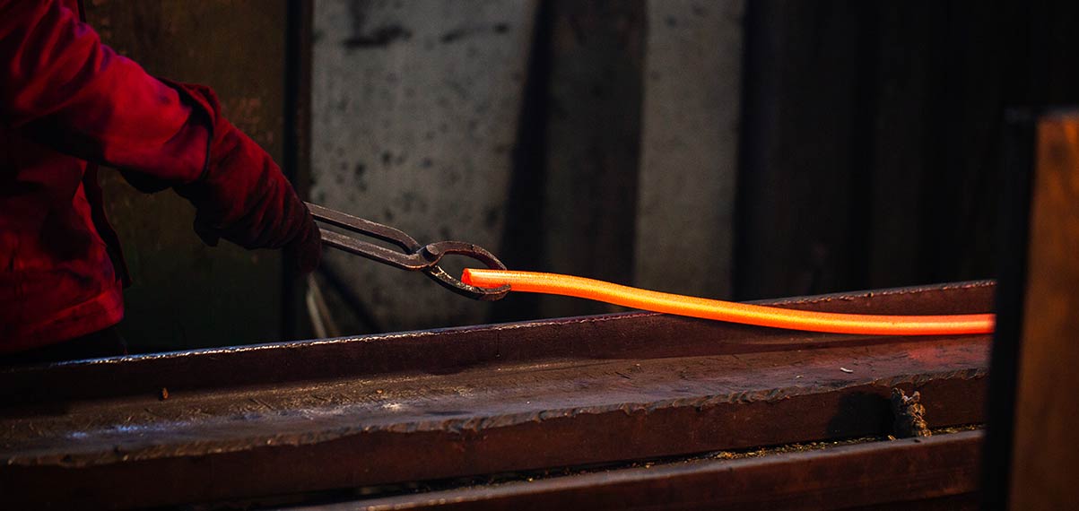
Equipment under the floor experiences the outside air temperature and the heat generated by its own electronics, and the resulting temperature range can span more than a hundred degrees. The board is also cycled through that range every day as the vehicle enters and leaves service.
The thermal cycling consequences are the same as in other long life applications, but with a longer expected life: solder joint fatigue on large components, delamination of the laminate and cracking of the plated barrels. A high glass transition laminate, a low expansion solder and careful component placement all extend the life, and the reasoning behind those choices is described in lead-free versus leaded solder.
Humidity, Contamination and Coating
Track environments include water spray, cleaning agents and, in coastal areas, salt. Once moisture and contamination reach a biased board, electrochemical migration begins, and the result is a leakage path that appears only in wet weather.
A conformal coating is standard practice for underframe equipment, and its specification has to name the material, the thickness and the areas to be masked. Coatings also need to resist the cleaning agents used on the vehicle, since a coating that dissolves in a wash is not protecting anything. The practice is set out in conformal coating and board protection.
Power Supply and Electrical Environment
The supply comes from the vehicle battery or from a converter fed by the traction system, and it carries transients from switching, from load changes and from the overhead line where one is used. The board has to tolerate those transients and, in the case of signalling equipment, also survive them without corrupting a decision.
Protection is arranged in stages at the input, with the first device at the connector and a second clamp close to the sensitive circuit, and the layout between them must not add the inductance that would let a transient bypass the protection. Where the electronics share an enclosure with the traction converter, the separation and shielding of the low level signals becomes a significant part of the layout work, following the principles in EMI suppression design principles.
Electromagnetic Compatibility
Rail vehicles have both strict emission limits and a hostile electromagnetic environment, and the equipment has to meet the applicable standards for both. Immunity is usually the harder of the two, because the sources include the traction drive, the pantograph and the signalling system itself.
Controlling the return current is the most effective single measure. A continuous reference plane, connectors filtered at the entry point and no long unshielded loops keep the currents where they were intended to flow. Equipment that shares a wiring route with the traction cables also benefits from separation and from a defined cable shield termination.
Service Life and Maintainability
A vehicle stays in service for thirty years, and the electronics may be replaced once or twice in that period. Components that become obsolete force a redesign, and a redesign of a safety related board triggers a new qualification, so designers often choose more conservative parts with longer availability.
Maintainability has an economic dimension. A board that can be tested as a module, with the test access and the self test functions designed in, is replaced in minutes rather than diagnosed in place. That is worth board area, and the calculation that justifies it is the cost of a train standing out of service.
Standards and Documentation
The applicable EN 50155 temperature class also decides whether the equipment needs heating or cooling at the extremes, and that decision affects the enclosure as much as the board. Rail electronics standards define the temperature classes, the supply voltage ranges, the transient requirements and the vibration and shock levels for equipment mounted in different locations on the vehicle. EN 50155 is the reference for rolling stock electronics, and it classifies equipment by its mounting position and defines the corresponding test conditions. The location determines the class, so the first design decision is where the equipment will be mounted.
The documentation set has to demonstrate conformity to those classes, which means test reports tied to the specific build, material declarations and a configuration record. A change of laminate, of a component supplier or of a coating material is a change to the product, and it has to be assessed rather than absorbed, because the qualification evidence applies to the configuration that was tested and not to a similar one.
Design and Manufacturing Practice
Practical rules follow from the environment. Use thicker copper where current is significant, keep the aspect ratio of plated holes moderate for barrel reliability, provide generous creepage on high voltage sections and give every heavy component a mechanical attachment.
On the manufacturing side, the processes that matter are the ones that cannot be verified by inspection afterwards, which is why conformal coating, bonding and plating all need controlled specifications and records. Building that evidence during production is far cheaper than reconstructing it when a fleet is being assessed, and the wider quality framework is described in PCB design quality characteristics.
FAQ
How long must the board last? The design life is usually stated in decades, with the understanding that some modules are replaced. That figure should drive the thermal and vibration analysis rather than being treated as a target.
Is a conformal coating always required? For equipment mounted outside a conditioned cab it is normal practice. Inside the cab the requirement depends on the enclosure and on the cooling arrangement.
What is the main cause of field failure? Solder joint fatigue on heavy components and contamination driven leakage. Both are design decisions rather than random events, and both are addressed by the layout and the coating.