Solder Mask and Paste Mask: Openings, Dams and Stencil
Two layers in a circuit board drawing are routinely confused. The solder mask is the permanent coating on the finished board, and the paste mask is a drawing of the openings in the stencil that deposits solder paste during assembly. They serve different purposes, they are made by different people and they are not interchangeable.
Getting them right is a matter of a few clearances, but getting them wrong produces defects that range from unsolderable pads to solder balls rolling across the assembly line.
The Two Layers and What They Mean
The solder mask layer defines where the coating is removed so that a pad is exposed. It is a physical feature of the board and it is evaluated by the fabricator against the copper artwork.
The paste mask layer defines where the stencil has an aperture, so that paste is printed onto the pad. It is a feature of the assembly tooling, it is evaluated by the assembly house against the component footprint, and it can be adjusted without changing the board.
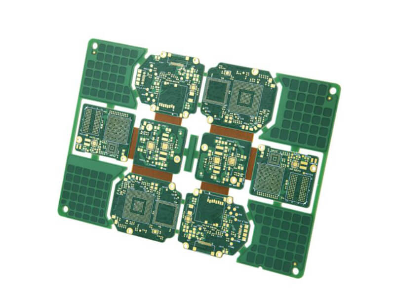
What the Solder Mask Does
The mask protects the copper from oxidation, prevents solder from bridging between adjacent pads during reflow and provides electrical insulation between conductors on the surface. It also defines the solderable area, which is why the mask opening is as important as the pad itself.
A mask that overlaps a pad reduces the area available for the joint, while a mask opening that is too large exposes copper beside the pad and risks a bridge to a neighbouring net. The opening is normally defined as the pad plus a small expansion on each side, chosen to match the registration tolerance of the fabricator.
What the Paste Mask Defines
The paste mask is the stencil design. Each aperture is usually the pad size modified by a factor that accounts for the stencil thickness and the paste volume the joint requires. On a fine pitch component the apertures are often reduced in the length direction to prevent bridging, and sometimes split to reduce the volume.
The stencil thickness is part of the design. A thin stencil with large apertures delivers a different volume from a thick stencil with small ones, and the ratio of the aperture area to the wall area of the stencil is the parameter that decides whether the paste releases cleanly.
Openings, Dams and Webs
Between two adjacent pads the mask forms a dam, and the width of that dam is limited by the pitch and by the registration tolerance. On a fine pitch part the dam can become so narrow that the fabricator cannot hold it, and the mask is then removed between the pads, leaving a single opening that covers the whole footprint.
That arrangement removes the insulation between the pads, so the assembly process has to be capable on its own. The decision belongs to the fabricator and the assembly house together, and the artwork should not assume one or the other without a note.

Solder Mask Defined and Copper Defined
When the mask opening is smaller than the copper pad, the pad is defined by the mask and the exposed area is determined by the opening. When the opening is larger than the pad, the pad is copper defined and the mask simply clears the copper with a margin.
The two behave differently in assembly. A mask defined pad has a smaller solderable area and less room for the joint, while a copper defined pad exposes more copper and is more tolerant of registration error. The choice affects reliability, especially on a package where the joint is small relative to the pad.
Stencil Design and Aperture Ratio
Paste release depends on the ratio of the aperture area to the aperture wall area. A ratio above about 0.66 releases paste reliably, and below that the paste tends to stay in the stencil rather than transferring to the pad.
When a fine pitch footprint drives the ratio below that value, the practical options are a thinner stencil, a smaller aperture on a larger pad, or a step stencil with a locally reduced thickness. Each has a consequence for the volume of paste delivered elsewhere on the board.
Common Mistakes in the Data
The most common error is exchanging the two layers by name. A paste layer sent to a fabricator produces a plausible looking board with the wrong mask openings, and a mask layer sent to a stencil house produces a stencil with the wrong apertures. The names and the file extensions in the data package should be checked deliberately.
The second mistake is treating both layers as identical copies of the pad. The paste aperture is frequently offset or resized relative to the pad, and copying the mask shape into the stencil removes the design intent that the assembly engineer would have applied.
Design Rules
Define the mask expansion from the fabrication capability, define the paste aperture from the stencil thickness and the required volume, and keep the two documented separately in the drawing set. Where the pitch forces a decision between a narrow dam and a single opening, record which one the design assumes.
gopcb builds boards with validated mask clearance against the copper artwork, and supplies the paste layer separately for stencil manufacture so that the assembly tooling reflects the design intent rather than a copy of the board data.
Where the Solder Dam Comes From
The solder dam is the strip of mask left between two adjacent openings, and its width is the difference between the pitch and twice the mask expansion. When a fabricator quotes a minimum dam width, that number is the practical limit of the process, because a narrower strip tends to lift during development or to wash away in the plating line. Designing a footprint with a dam below that limit produces a board that cannot be built as drawn, and the fabricator will either widen it or remove it without telling the designer which choice was made.
On a fine pitch package the dam is often removed deliberately, so the mask presents one opening across the footprint. That is a legitimate choice, but it changes the assembly process, because the mask no longer prevents a bridge between pads and the paste volume has to be controlled more tightly to compensate. The decision should be documented on the fabrication drawing rather than left to the CAM operator.
Aperture Design for Difficult Components
Some components need the paste aperture to differ from the pad in both dimensions. A connector with a long pad is often split into two or three smaller apertures so that the paste volume is reduced without changing the stencil thickness, and a large thermal pad is divided into a grid for the same reason. Each of those changes is applied to the paste layer only and has no effect on the board.
The offset between the aperture and the pad matters as well. Where a component lead sits at the edge of a pad, shifting the aperture slightly towards the body of the pad improves the joint without increasing the risk of a bridge. That adjustment is a normal part of stencil design, and it is one of the reasons the paste layer should be generated by the assembly engineer rather than copied from the mask layer.
FAQ
Are the solder mask and paste mask the same file? No. The solder mask is a board feature and the paste mask is a stencil feature. They usually have different shapes even when they look similar on a screen.
Why is the paste aperture often smaller than the pad? Because the stencil thickness and the paste volume have to be matched to the joint. Reducing the aperture prevents excess paste and bridging on a fine pitch part.
Can the mask opening be smaller than the pad? Yes, that is a mask defined pad. It is common on packages where the mask dam between pads has to be maintained, but it reduces the solderable area.
Related reading: PCB manufacturing tolerances, PCB silkscreen design rules, PCB manufacturing processes, and PCB design quality characteristics.