Underfill Dispensing in PCB Assembly: Materials, Methods and Control
Underfill is one of the few assembly processes that exists purely to compensate for a materials problem. A silicon die and an organic board expand at very different rates when they warm up, and the solder joints between them absorb all of that mismatch. Underfill spreads the strain across a larger volume of material, and in doing so it can multiply the thermal cycling life of a package by an order of magnitude.
What Underfill Does for a Soldered Joint
A soldered joint is a small piece of metal with limited fatigue life. Under thermal cycling it creeps, cracks at the intermetallic interface and eventually fails. Underfill changes the mechanical situation rather than the metallurgy. The cured polymer mechanically couples the package to the board, so the mismatch is distributed through the adhesive instead of concentrating at the solder joints.
The technique began in ceramic package assembly, where large bodies and stiff substrates made the problem acute, and moved into board level chip packaging as flip chip and area array packages became common. It is now standard for fine pitch devices where a single cracked joint means a scrapped assembly, and for products that must survive drop and shock loading. The package types involved, and the substrates they are built on, are described in IC package substrate, while placement accuracy issues are covered under SMT component shift causes.
Capillary Underfill and No-Flow Variants
Capillary underfill is applied after soldering. A needle dispenses a bead of material along one or two edges of the package, and capillary flow draws it into the gap under the die or the package body until a fillet forms on the opposite side. How fast that flow advances depends on gap height, filler particle size, viscosity and board temperature. The process depends on a clean, flux-free surface, a suitable gap height and a material whose filler particles are small enough to pass through that gap.
No-flow underfill reverses the order. The material is dispensed onto the pads before component placement, fluxes the joints during reflow and cures in the same thermal cycle. It removes an entire process step and suits very fine pitch devices, but the material must simultaneously flux, cure and flow, which constrains the chemistry. Edge bonding, where adhesive is applied only at the package corners, is a cheaper middle ground for shock resistance.
Dispensing Methods: Time-Pressure, Auger and Jetting
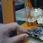
Time-pressure dispensing is the simplest approach. A pulse of air displaces material through a needle, and the deposited volume depends on viscosity, needle geometry and the pressure pulse. It is inexpensive and widely used, but the deposit varies as the material changes temperature or begins to cure inside the needle.
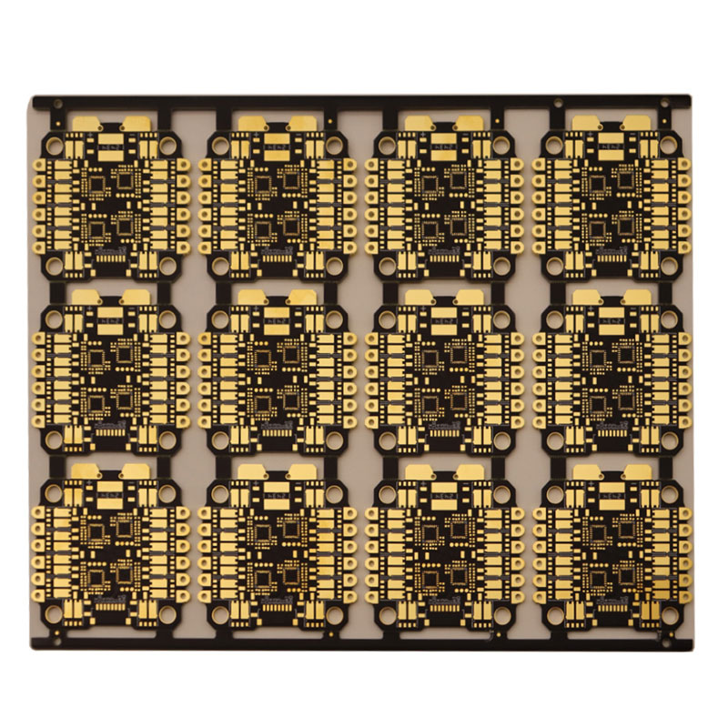
Positive displacement systems remove that variability. An auger screw meters a defined volume per revolution, so the deposit is volumetric rather than pressure driven. Jetting goes further by ejecting a droplet without touching the board, which allows fast, non-contact dispensing around tall components and over uneven surfaces. The same jetting technology is used to apply conformal coating, where selective deposition replaces masking.
Cure, Voiding and Keep-Out Control
Voids are the main defect. They come from moisture absorbed in the board or the package, from flux residue that outgasses during cure, and from an uneven flow front that closes around a pocket of air. Pre-baking the assembly, controlling the flow path so that the material advances as a single front, and using a cure profile that ramps gradually rather than sharply all reduce voiding. Moisture sensitivity levels and bake schedules for the packages involved are covered in moisture sensitive devices on PCB.
Keep-out rules matter just as much. Underfill must not wick into connectors, test points, shielding frames or mechanical features, and it must not bridge to adjacent components. Machine programming has to account for board tolerance, since the fillet must be visible and complete without spreading beyond the permitted area. Establishing those boundaries before production is far cheaper than reworking contaminated hardware.
Thermal Cycling, Rework and Inspection
Filled epoxy materials, typically carrying a substantial proportion of silica filler, are chosen so that the cured adhesive has a coefficient of thermal expansion closer to the solder than to the board. That is what produces the reliability gain, verified by cycling test boards between temperature extremes and inspecting the joints by cross-section or acoustic microscopy.

The cost of that reliability is rework. Once cured, underfill bonds the package to the board, and removing a device without damaging pads or neighbouring parts is difficult and slow. Underfilled assemblies are usually treated as non-repairable, so test coverage and first pass yield become the economic levers. Visual inspection confirms the fillet and the keep-out compliance, while X-ray and scanning acoustic microscopy reveal what the eye cannot.
Specifying a Dispensing Process
A workable specification defines the material, the fill pattern, the fillet dimensions, the permitted void fraction, the cure schedule and the inspection method. It also defines what happens to the process when the board changes: a new package height, a different pad finish or a revised stencil can all alter how the material flows.
Because the process is sensitive to temperature and time, the shop floor needs control over board preheat, material pot life and dispense timing. At gopcb we treat underfill, dispensing and coating as part of the assembly flow rather than as a finishing step, so that keep-outs and cure windows are agreed before the first panel is built.
Surface Condition and Material Selection
Underfill bonds to whatever the soldering process left behind. Flux residue, mould release agents and fingerprints all reduce adhesion, and a weak bond is worse than no bond because it transfers stress unevenly. Cleaning before dispensing, or choosing a no-clean chemistry that leaves a compatible residue, is therefore part of the underfill decision rather than a separate housekeeping step.
Material selection follows the gap. Filler particle size must be small enough to pass under the package without filtering out and blocking the flow, which is why fine pitch devices restrict the filler content and therefore the achievable thermal expansion match. Viscosity, pot life, cure temperature and the glass transition of the cured polymer all have to be considered together, and the supplier data should be confirmed on the actual assembly rather than assumed from the datasheet.
Common Process Problems and Their Causes
Incomplete fill is the most frequent complaint, and it usually traces back to insufficient board preheat, a gap that is too small for the filler, or dispensing that began before the assembly reached a stable temperature. Material that has partly cured in the needle behaves differently from fresh material, so pot life discipline affects deposit volume as much as chemistry.
Contamination is the second category. Adhesive that wicks onto a connector contact, a test pad or an optical surface cannot always be removed without damage, so keep-out zones must be defined geometrically and verified on the first article. Finally, cure profiles that ramp too quickly generate voids and internal stress, which show up later as delamination rather than as an immediate defect.
FAQ
When is underfill actually necessary? When the package is large relative to the board, when the product sees repeated thermal cycling or mechanical shock, or when a single cracked joint would scrap an expensive assembly. Small packages on stable boards usually do not need it.
Why does underfill void so often? Moisture, flux residue and trapped air are the three causes. Baking the assembly, cleaning thoroughly and controlling the flow front so that it advances evenly removes most of the problem.
Can an underfilled package be replaced? Only with difficulty. The cured material has to be removed mechanically or thermally, and the process risks pad and laminate damage. Most production lines treat it as a non-reworkable step.