Core Board PCB Classification: Layers, Materials and Construction
A core board is the small, self-contained module that carries the processor, memory and essential support circuitry, leaving the application-specific design to a larger carrier board beneath it. Because the term describes a role rather than a single product, core boards come in many constructions. Classifying them by layer count and by base material is the quickest way to understand which one suits a given product.
What a Core Board Is
The printed circuit board is the carrier of the components and one of the most important parts of any electronic assembly. On a core board, that carrier function is deliberately concentrated: the module provides the computing core and the interfaces it needs, and the developer builds the surrounding product around it.
That division of labour is why core boards appear in so many forms. A wearable device, an industrial controller and a camera module all need a computing core, but they impose completely different mechanical and environmental requirements on the board carrying it. The classifications below describe how those requirements are met.
Classification by Layer Count
The first way to classify a core board is by the number of circuit layers. The three families are single-sided, double-sided and multilayer. Multilayer boards typically run from three to six layers in common products, while complex designs reach into the teens and beyond.
Layer count is not a measure of quality, but of routing demand. A design with few connections and modest component count is well served by one or two layers, while a dense processor module with a fine pitch package and controlled impedance requirements cannot be built without multiple layers and reference planes.
Single-Sided and Double-Sided Construction
On the most basic printed circuit board, the components are concentrated on one side and the conductors on the other. Because conductors appear on only one face, this is called a single-sided board. The layout is heavily constrained, since tracks cannot cross one another and each connection must find its own route around the others.
Double-sided boards carry conductors on both faces. To connect them, the two sides require an electrical link, and that link is the via: a small hole in the board filled or coated with metal so that it joins the conductors on each face. Because the available area doubles and routes can pass to the opposite side, a double-sided board supports considerably more complex circuits than a single-sided one, which is why it replaced single-sided construction for most products.
Multilayer Construction and Even Layer Counts
Multilayer boards increase the available routing area further by stacking several double-sided circuits, separating them with insulating layers and bonding the assembly together. The layer count refers to the number of independent routing layers, which normally comes to an even number and always includes the two outer faces.
The reason for the even count is mechanical symmetry. A stack built with an odd number of copper layers tends to bow when the assembly cools after lamination, because the copper distribution on either side of the centre is unequal. Adding a layer is usually cheaper than adding a balancing construction to an odd stack. Balanced constructions are discussed in balanced stackup and odd layer counts.
Classification by Base Material: Flexible Boards
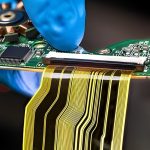
The second classification looks at the material rather than the layer count. Flexible printed circuits are built on a flexible base material, which allows the board to bend when the assembly is installed. That flexibility is their entire purpose: it permits a board to be folded into a housing, follow a curved surface or move with a mechanism.
Flexible circuits are widely used in aerospace, military equipment, mobile communications, portable computers, computer peripherals, personal digital assistants, digital cameras and similar products. In most of those applications the flexible section performs a specific job, such as routing signals through a hinge or connecting two rigid sections that must move relative to one another.
Rigid and Rigid-Flex Construction
Rigid boards are made from paper-based material for simple single-sided work, or glass cloth based material for double-sided and multilayer boards, impregnated with phenolic or epoxy resin and laminated with copper foil on one or both faces. The defining property is that the material resists bending and provides mechanical support to the components mounted on it.

Rigid-flex combines both types in one board. A single printed circuit contains one or more rigid regions and one or more flexible regions, laminated together so that the finished part provides the support of a rigid board where components are mounted and the bending behaviour of a flexible board where the assembly must fold. That combination is what allows three-dimensional assembly, in which the board itself becomes part of the mechanical structure. Stackup considerations are described in rigid-flex layer stackup design.
Matching the Classification to the Application
Choosing between these options comes down to the mechanical requirement first and the electrical one second. If the assembly must fold or move, a flexible or rigid-flex construction is the only option that satisfies it. If it must simply support components and carry dense routing, a multilayer rigid board is cheaper and easier to manufacture.
Within the rigid family, the layer count follows the routing demand rather than any preference. A core board that carries a fine pitch processor with controlled impedance interfaces will need reference planes and therefore multiple layers, while a simple interface module may be entirely adequate as a double-sided board. Deciding this early keeps the fabrication cost proportionate to the function; the module approach itself is described in module board design.
Where Core Boards Fit in a Product
The core board approach changes how a product is developed. Instead of designing the processor, memory and high speed interfaces from scratch, the developer buys or reuses a module that already contains them and concentrates engineering effort on the application circuitry that differentiates the product. That shortens development and reduces the risk attached to the most demanding part of the design.
The interface between the module and the carrier becomes the critical design element. Its connector carries power, high speed buses and control signals across a mechanical joint, so the pin assignment, the impedance of each group and the return path all have to be planned together. A poorly specified interface can erase the benefit of using a module at all.
Cost behaves differently in this model too. The module is more expensive per unit area than a plain board, but it removes the need for a high layer count design, impedance expertise and a long qualification cycle. For products built in modest volumes, that trade usually favours the module; at very high volumes, integrating the same circuitry onto a single board often becomes cheaper. The choice should be revisited as volume grows rather than fixed at the start of the project.
FAQ
Is a core board always multilayer? No. It is classified by layer count like any other board, and simple core modules are built as double-sided boards. Multilayer construction appears when the routing demand requires it.
Why are multilayer boards usually an even number of layers? Because an unbalanced stack tends to warp after lamination. Keeping the construction symmetric about the centre is easier than compensating for an odd layer count.
When is rigid-flex worth the extra cost? When the assembly must fold into a three-dimensional shape or when a moving joint is required. If neither applies, separate rigid and flexible boards joined by a connector are usually cheaper.