
Metal Core PCB: Aluminium Substrates and Thermal Design
When a component has to lose several watts through the board beneath it, a glass reinforced epoxy substrate becomes the bottleneck. A metal core board replaces the structural laminate with aluminium or another metal and separates it from the copper circuit by a thin dielectric layer. The result is a board that conducts heat an order of magnitude better than a conventional one, at the cost of some freedom in design.
What a Metal Core Board Is
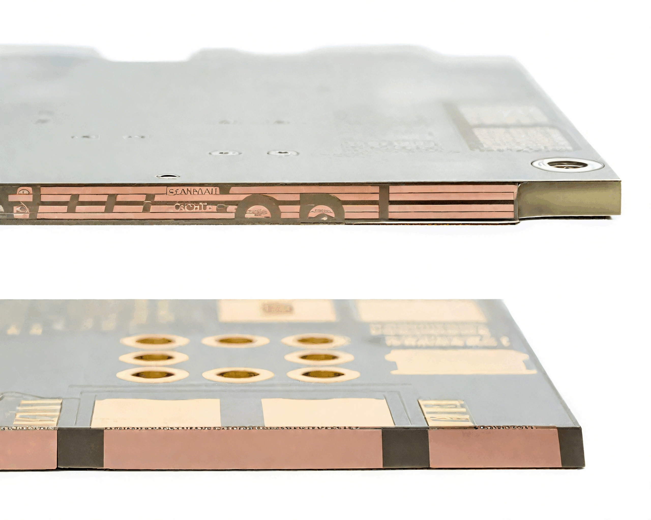
The construction is simple to describe: a metal base, a dielectric layer and a copper foil circuit on top. The dielectric provides the electrical insulation and the bond, and it is thin, typically tens of micrometres, so that the thermal path is short. The aluminium substrate is usually chosen because it is light, cheap and a good conductor of heat, though copper and steel appear where the thermal or magnetic requirement calls for them.
Most metal core boards are single sided, with the circuit on one face and the metal on the other. Where more layers are needed, the additional layers are built on the circuit side, and the metal core continues to act as the heat spreader and the mechanical base.
The Dielectric Layer
The dielectric is the critical material. It has to bond to the metal and to the copper, withstand the thermal cycling of the application, provide the dielectric strength the circuit needs, and conduct heat as well as possible. The formulations used for this are filled polymers, and their thermal conductivity is many times that of ordinary laminate while remaining far below that of the metal itself.
The layer is also the electrical insulation between the circuit and the metal base, and its thickness is chosen to satisfy the working voltage with a margin. Where the circuit is mains connected or the metal base is accessible to a user, the thickness and the dielectric strength are safety parameters, and the temperature rating of the material limits how hot the assembly may run.

The Thermal Path
Heat leaves a component through its solder joint into the copper, crosses the dielectric and spreads in the metal base. Each step has a thermal resistance, and the total is what determines the junction temperature. The dielectric usually dominates, because it is thin but its conductivity is modest, which is why the thickness is kept as small as the voltage rating allows.
Increasing the copper area under the component reduces the spreading resistance on the circuit side, and increasing the thickness of the metal base reduces it further on the other. The metal base also spreads heat laterally, so a board bolted to a chassis conducts into the chassis as well as into the air. Copper thickness and thermal spreading are related in the same way as on any board, and the calculation is described in trace width and current calculation.
Applications
Lighting was the first large application, because a light emitting diode converts most of its input into heat rather than light and cannot tolerate a high junction temperature. Power supplies and motor drives followed, where the switching devices dissipate heat that must leave a small volume. Automotive electronics uses metal core boards where a device sits in a hot location and the only available heat sink is the housing.
The common thread is a component that produces a concentrated heat load and an environment that provides no airflow. A metal core board turns the whole board into a heat spreader, which is more effective than adding copper to a laminate whose thermal conductivity remains poor.
Design Rules
The circuit rules are similar to those of a single sided board, with a few additions. Thermal relief is often required on pads connected to large copper areas, because the metal below conducts heat away and makes soldering difficult. The copper distribution should be balanced so that the board does not bow when the assembly is heated, and large areas of copper should be avoided where they would create a stress concentration at the edge of the board. The behaviour of the copper and the base through the thermal cycle is the same class of problem as in a conventional multilayer board, and it is described in PCB dimensional stability and expansion.
Mechanical features follow the metal. Holes drilled through aluminium for mounting are usually plain rather than plated, and the metal base can be tapped or shaped so that the board mounts directly to a housing. Where the board is bent or pressed into a shape, the design of the outline is part of the thermal design, because the shape determines how well it contacts the surface it is mounted to.
Limits and Trade Offs
A metal core board cannot carry the density of a multilayer board. Single sided construction limits the routing, and the assembly of the second side is impractical without an insulating layer. Where a design needs both high density and good thermal performance, the usual answer is a conventional multilayer board with thermal vias into a metal heat spreader, or a metal core board with the digital circuit on a separate small board.
The other limitation is weight and cost. Aluminium is heavier than laminate and the material and process cost more, so a metal core board is chosen when the thermal requirement justifies it rather than as a general improvement. Where a few watts have to leave a small area and there is no other path, it is usually the simplest answer available.
Assembly and Mounting
Assembly is similar to a single sided surface mount board with two differences. The board retains more heat during reflow because of its mass, so the profile has to account for it, and the thermal relief on the pads has to be adequate for the heat that the metal base draws away from the joint. Where a large device is soldered to a large copper area, a longer soak and a slightly higher peak are often needed.
Mounting is where the design gains its advantage. The board is usually fixed to a metal housing with a thermal interface material between, and the flatness of both surfaces and the thickness of the interface determine the extra resistance. Bolting the board at the hottest area, and using the interface material across the whole contact area rather than only at the fasteners, is what makes the theoretical thermal path real.
Verification
Thermal verification is by measurement rather than by calculation alone. A thermocouple or an infrared camera is used to observe the component body and the board surface with the assembly operating at full load and in the intended orientation, because convection depends on orientation and the enclosure changes the airflow.
The dielectric is verified electrically at the working voltage and, where it is a safety parameter, at the test voltage the standard requires. Mechanical verification covers the flatness of the board, the quality of the bond between the dielectric and the metal after thermal cycling, and the integrity of any mounting features, because a delamination of the dielectric layer would remove both the insulation and the thermal path at once. Where the board is coated for protection, the coating has to tolerate the same temperature excursion as the dielectric, and the considerations are described in conformal coating for board protection.
FAQ
Can a metal core board have two sides of components? Only with an additional insulating layer, which defeats much of the thermal advantage. Single sided assembly is the normal arrangement.
Is aluminium always the base material? It is the common choice for cost and weight. Copper is used where the thermal requirement is higher and steel where the mechanical or magnetic properties matter.
Why is thermal relief needed on a metal core board? Because the metal conducts heat away from the pad during soldering, which makes a good joint difficult without a slight increase in thermal resistance.