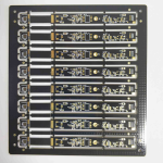
Castellated Holes and Module Edge Design for PCB Modules
A module that solders onto a carrier board like a component has no pins and no connector. Its interface is a row of castellated holes along the edge, each one a plated half cylinder that wets to a pad on the motherboard. The idea is elegant and the execution is unforgiving, because every parameter that makes a normal plated hole reliable has to survive being cut in half. This guide covers module edge design for castellated modules.
What a Castellated Hole Is
A castellated hole begins life as an ordinary plated through hole placed on the final board outline. When the outline is routed, the tool passes through the centre of the hole and removes roughly half of it, leaving a plated crescent that is open along the module edge but still connected to the copper barrel and any inner layers it served.
Functionally it is a solderable pad with a vertical surface. The joint forms on the inside of the half cylinder and on the pad beneath it, so the joint is stronger than a flat land alone. Because the wall is exposed, the plating quality of the barrel becomes a cosmetic and a mechanical concern at the same time.
How the Half Hole Is Formed
Two processes are used. In the first, the holes are drilled and plated on the full panel and the castellation is created later by a router bit or a V cut that removes half the barrel. In the second, the edge is profiled before plating so that the plating wraps over the cut edge, which also produces edge plating on the same pass.
Routing is preferred over sawing because a saw can smear resin and tear the copper wall. The depth of the cut sets how much of the barrel remains. Cut too deep and the remaining wall is thin and fragile, cut too shallow and a lip of laminate is left that prevents the joint from forming. The tolerance on that depth belongs in the fabrication drawing.

Plating Quality and the Halo
The exposed wall of a castellated hole should show a continuous, evenly distributed copper layer. A dark or thin band indicates plating that did not fully cover the barrel, and that is where a crack will start. The halo, which is the ring of glass fibre and resin visible around the copper, should be uniform rather than ragged, because a ragged halo points to mechanical damage during routing.
Barrel plating thickness on a castellated feature is usually called out to the same specification as any other plated hole, commonly 20 to 25 microns of copper. Where the module will see thermal cycling, thicker plating and a well controlled etch help, as described in our notes on pcb hole copper.
Module Edge Geometry and Routing Depth
The nominal cut is normally through the hole centre, which leaves a half cylinder. Some designs allow the cut to sit slightly past centre so that the opening is a little more than half, giving the solder better access. Others cut short of centre to preserve more wall. Either choice has to be applied consistently, because a mixed edge is difficult to place and difficult to inspect.
Spacing between castellations is set by the router tool and by the land pattern on the carrier board. A pitch below about 0.8 mm becomes difficult to route cleanly because the remaining web between holes is thin. Where a fine pitch is unavoidable, a smaller cutter and a slower feed are used, and the outline tolerance should be stated rather than assumed. Our guide to board outline tolerance rules explains how those limits are set.
Land Pattern and Solder Joint Design
The land pattern on the carrier board extends beyond the module edge so that solder can form a fillet on the outside of the castellation. A common rule is to extend the pad by roughly 0.5 mm past the edge, with the pad width matching the castellation diameter and a small clearance to the neighbouring pad. The pad must be long enough to be visible after assembly, because that fillet is what the inspection looks for.
Ground and thermal pads need more thought. A large copper pour connected directly to the land draws heat away during soldering and produces a cold joint, so thermal relief spokes are used where the joint must be reflowed. Where the pad is also a thermal path, the number and width of the spokes become a design trade off rather than a default.
Assembly and Solder Wicking
Solder wicks into a castellated hole by capillary action, which is helpful up to a point. Enough solder should climb the wall to form a visible fillet, but too much will travel to the opposite side of the module and can bridge to an adjacent castellation. The stencil aperture controls the volume, and the aperture is usually sized as a percentage of the pad area rather than as a simple one to one opening.
Modules with a large thermal mass are often reflowed twice, once for the module and once for the rest of the assembly, and the castellations see both cycles. Choosing a paste with a suitable alloy and keeping the module flat during reflow avoids the tilted joints that appear when one side of a long edge melts before the other.
Panelisation and Breakaway Strategy
Castellations are fragile until the module is separated from its panel, so the breakaway method matters. Tab routing with small perforated tabs keeps the edges supported through assembly and test, and the tabs are placed so that the router path does not clip a castellation when the module is removed.
V scoring is generally unsuitable for a castellated edge because the score line and the castellation compete for the same strip of material. Where tabs are used, they should be positioned between castellations rather than on top of one, and the tab width should be large enough to survive handling but small enough to snap cleanly. Our guide to breakaway tab design covers the trade offs.
Inspection, Test and Rework
Visual inspection confirms that the castellation is open, that the plating is continuous and that the fillet is present on the carrier pad. Optical inspection from a shallow angle is more informative than a top down view, because the wall of the hole is where the defects hide. Automated optical inspection can be programmed for the edge, but the lighting has to be arranged to illuminate a vertical surface.
Rework of a castellated joint is possible with a fine tip and local heating, but repeated rework damages the plating on the wall. Where a joint must be reworked, adding fresh solder rather than reheating the existing fillet gives a better result. The general forms of these features are summarised in our article on pcb hole types explained.
Documentation and Fabrication Notes
The module drawing should specify the castellation diameter, the pitch, the cut depth and its tolerance, the plating thickness, whether edge plating is continuous along the whole edge or only at the holes, and the panel breakaway method. Vague notes such as half holes are a reliable way to receive modules that do not fit the carrier footprint.
It also helps to state the assembly process and the intended solder volume, because a fabricator who knows the module will be reflowed twice will handle the plating and the surface finish differently. A simple note about the finish, whether it is immersion gold or a solderable organic coating, avoids an oxide layer that resists wetting on the exposed wall.
FAQ
What is the difference between a castellated hole and edge plating? A castellated hole is a specific plated through hole cut in half at the outline, while edge plating is a continuous copper layer on the cut face. The two are often produced in the same profiling step, but only the castellation gives a defined solderable feature.
Can castellations carry current? Yes, and they carry it well because the wall adds surface area. The practical limit is set by the plating thickness, the hole diameter and the number of castellations used for the net. Several half holes in parallel behave much like several vias in parallel.
Why does a castellated module fail after reflow? The usual causes are a cut that removed too much of the barrel, plating that did not fully cover the wall, or a land pattern that is too short to form a fillet. All three are visible before assembly, which is why incoming inspection of the edge is worthwhile.