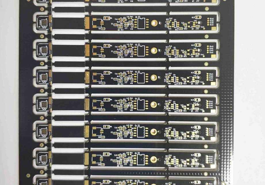
Heavy Copper PCB Design and Etching Tolerance Explained
Heavy copper boards look simple to design because the traces are wide and the geometry is coarse. In practice they behave like a different process. The etch that shapes a one ounce layer cannot shape a four ounce layer in the same way, and the difference shows up as a trace width that is narrower than the designer drew. This guide explains heavy copper design and its etching tolerance.
What Counts as Heavy Copper
Ordinary rigid boards use copper foil of half an ounce or one ounce per square foot, which is about 17 or 35 microns thick. Heavy copper usually means three ounces and above, and the term is applied to boards that reach five, ten or even twenty ounces in specialised power applications.
At those weights the copper is no longer a thin skin on the laminate. It carries mechanical stiffness, it changes the thermal behaviour of the board, and it dominates the fabrication sequence. A ten ounce inner layer is often built by laminating several sheets of thinner copper and plating between them rather than by starting from a single thick foil.
How Copper Thickness Changes the Etch
Etching removes metal sideways as well as downwards. On a thin foil the sideways removal is small relative to the thickness, so a fine trace survives with a nearly rectangular section. On thick copper the etchant has to travel much further to clear the spaces, and during that time it continues to attack the sides of the traces.
The result is a trapezoidal section: the trace is narrower at the top than at the base, and the wider the copper, the more pronounced the slope. That sloped wall is normal rather than a defect, but it has to be anticipated, because the trace width quoted on a drawing refers to the dimension at the copper to laminate interface.
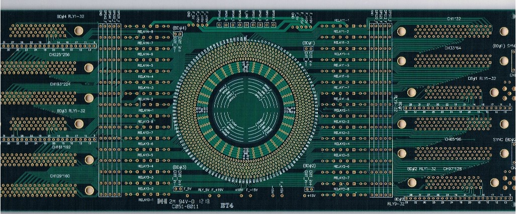
Etching Tolerance and Trace Width Control
The etching tolerance on a heavy copper layer is looser than on a one ounce layer. A common allowance is plus or minus 25 microns on standard foil, widening to 50 microns or more as the weight increases. A designer who specifies a trace width without considering that band may receive a conductor that is materially thinner than the current calculation assumed.
The practical response is to specify a nominal width that is generous and to state the minimum acceptable width separately. If a trace must carry a given current, the current capacity should be calculated from the minimum width after etching, not from the nominal. Our article on the pcb etching process describes how the tolerance arises.
The Etch Factor and Minimum Space
Fabricators describe the behaviour with an etch factor, which relates the depth of the etch to the sideways undercut. The factor is process dependent, and it determines the smallest space that can be cleared reliably for a given copper thickness. A space that is trivial on one ounce copper can be impossible on six.
This is why minimum space, not minimum trace width, is usually the limiting rule on a heavy copper board. Where a tight space is unavoidable, the fabricator may use a two stage etch or a thicker resist, both of which affect cost. Asking for the achievable minimum at the quotation stage saves a redesign later.

Plating Buildup and Thickness Verification
On a plated heavy copper board the finished thickness includes the original foil plus the copper plated in the holes and on the surface. The plating adds to the trace as well as to the barrel, so a four ounce start can finish close to five ounces after plating. That extra copper is useful for current but it also narrows the spaces further.
Verification is done by microsection, in which a sample is potted, ground and polished so the copper thickness and the wall slope can be measured directly. The section is the only reliable way to confirm both the base foil and the plating, and it is the reason heavy copper jobs quote a longer lead time. Our guide to pcb plating thickness explains how the measurement is specified.
Current Capacity and Thermal Design
Current capacity depends on the cross sectional area of the trace and on how much heat the board can remove. A wide trace carrying many amperes will still overheat if it is surrounded by poor thermal paths, and it will run cooler if it is spread over a large area or connected to internal planes that act as heat spreaders.
The usual approach is to calculate the required area from the acceptable temperature rise, then check that the resulting width fits the layout at the minimum etched dimension. Where it does not, the design moves to a plane, to a parallel connection through several layers, or to a busbar soldered onto the board. Our notes on pcb current capacity for 100a work through that calculation.
Copper Balance and Thieving
Heavy copper layers distort the laminate during lamination and etching. A layer with dense copper on one side and open laminate on the other will curl, and the resin will flow unevenly. The remedy is to balance the copper distribution across each layer and, where balance is impossible, to add thieving pads or a grid of dummy copper.
Thieving has to be planned rather than dropped in at the end, because it changes the electrical environment near the signal it surrounds. On a power board the thieving can usually be tied to a net that is thermally similar, but it should never be left floating in a way that creates an unintended antenna. Our article on the copper balance and thieving guide covers the rules.
Layout Rules for Heavy Copper Boards
Keep the copper geometry coarse. Round the corners of wide traces and pads, because a square corner on thick copper is a place where the etchant stalls and where thermal stress concentrates. Avoid narrow necks between wide regions, since the neck is the first place the etchant over works and the first place a current density problem appears.
Vias in thick copper are equally constrained. Drilling through a heavy layer is slower and the barrel must be plated to a thickness that suits the current, so via count and via size should be planned with the fabricator. Where a via must carry high current, several vias in parallel are preferable to one large hole, and their placement should follow the current path rather than convenience.
Documentation, Cost and Lead Time
The drawing for a heavy copper board should state the copper weight of each layer, the minimum finished trace width and the minimum space, the plating thickness, the etch tolerance you are willing to accept, and whether the copper weight refers to the base foil or the finished thickness. Ambiguity here is expensive, because the two interpretations differ by a full plating step.
Cost rises with both copper weight and the number of heavy layers, and lead time rises because etching and lamination take longer and because microsection is usually required. The thermal aspects of these designs overlap with general board level practice, which is described in our notes on pcb thermal management design.
FAQ
Is heavy copper the same as thick copper foil? Not exactly. The two descriptions overlap, but heavy copper refers to the finished conductor weight, which includes plated copper, while thick foil refers to the starting material. On a heavily plated board the finished weight can be a full ounce above the foil.
Why is my etched trace narrower than the drawing? Because etching removes copper sideways as well as downwards, and the effect grows with thickness. The drawing dimension normally refers to the base of the trapezoid, so the top of the trace measures less, and the tolerance band is wider than on thin copper.
Can heavy copper boards use fine pitch components? They can, but the fine pitch area is usually formed on a thinner layer or on an outer layer that is plated after the heavy inner layers are finished. Mixing ten ounce copper with a 0.4 mm pitch device on the same layer is not practical.