Backplane PCB Design: Passive, Active and High-Speed
A backplane does almost nothing on its own, and that is the point. It carries no processing, no firmware and usually no user-facing function. Its job is to let a set of plug-in modules share power and talk to one another through a defined physical and electrical interface, and to do it for years without a single marginal connection.
What a Backplane Actually Does
Physically it provides the structure that holds the card cages and the connectors that the modules plug into. Electrically it distributes power to every slot and carries the signals that pass between modules.
That combination makes it the most mechanically and electrically stressed board in most systems. It is large, it usually needs many layers, every connector is a potential impedance discontinuity, and it has to survive repeated insertion and removal of modules over the life of the product.
Passive and Active Architectures
A passive backplane PCB contains connectors, planes and routing, and nothing else. It relies on the modules to drive and terminate every signal. The advantage is simplicity and reliability, because there are no active components to fail and no configuration to manage.
An active backplane adds buffers, repeaters, switches or a management controller, which allows longer channels and more slots than a passive design could support. The trade is complexity: the active devices need their own power and cooling, they consume a share of the reliability budget, and their failure takes down more than one slot.
Layer Count and Stackup
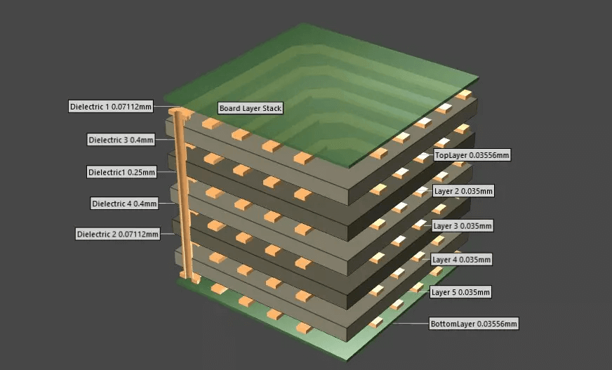
Backplanes are the boards where layer count reaches its practical peak. Eight to thirty-two layers is the normal range, with the higher figures appearing where many high-speed channels must be routed from every slot to every other slot or to a central switch.
The stackup is planned around the connector pin fields rather than around the routing. Each connector presents a dense array of pins on a fixed pitch, and escaping those pins through the remaining layers is what sets the layer count. Dedicated ground and power planes are essential, and the signal layers between them are usually paired so that every high-speed net has a continuous reference.
Connector Interfaces and Standards
Backplanes exist to serve a connector standard. The choice of standard fixes the mechanical format, the pin assignment and the impedance the system expects, so it is usually made before the board design begins.
The connector interface then drives the layout. Pin fields must be escaped without introducing stubs, differential pairs must be routed with consistent spacing through the connector footprint, and the ground pins in the connector must be connected to the plane with low inductance so that the return path is continuous across the interface.

Signal Integrity on a Long Channel
A backplane channel is long by definition. The path runs from a driver on one module through a connector, across the backplane, through a second connector and into a receiver on another module, which is often a distance measured in tens of centimetres.
That length makes insertion loss and skew the dominant concerns. At multi-gigabit rates the loss of a long channel is significant even on a good laminate, and the difference in propagation delay between two traces that should be matched becomes a timing problem rather than a rounding error. Impedance control has to hold through every part of that path, including the connectors, which is why the connector specification and the board specification are usually written together.
Materials
Standard FR-4 is adequate for moderate rates and shorter channels, and it remains the economical choice for many industrial and telecom backplanes. As data rates rise, the dielectric loss of the laminate becomes a larger share of the total link budget, and a low-loss material is required to keep the channel within its loss target.
Hybrid stackups are common. The high-speed channels are routed on layers built from a low-loss laminate, while the power, control and low-speed signals stay on ordinary FR-4. The two materials are bonded into one panel, which keeps the cost proportional to the area that actually needs the performance.
Fabrication and Assembly
Fabrication follows the standard multilayer sequence with a few additions. Because the boards are large, registration across the full panel is harder, and panel handling becomes a significant process consideration. Board thickness and flatness matter more than usual, since a warped backplane will not allow modules to seat properly.
Assembly adds the connectors, which are usually press-fit rather than soldered. A press-fit connector is inserted into a plated hole with an interference fit, forming a gas-tight connection without solder. That places specific requirements on the hole diameter tolerance and the plating thickness, and it means the connector is a mechanical feature of the board as much as an electrical one.
Mechanical and Reliability Requirements
Insertion force is the defining mechanical load. A module being pushed into a slot applies force through the connector into the board, and a large backplane may carry dozens of such connectors. Board thickness, stiffeners and mounting points all have to be designed so that the board does not flex enough to crack a joint or damage a connector.
Thermal considerations follow from the same scale. A fully populated chassis concentrates heat, and the backplane has to conduct heat away from the connectors into the chassis structure as well as routing power to the modules that generate it.
Telecommunications, Data Centre and Industrial Systems
Telecommunications equipment is the classic application, where a chassis of line cards shares a switched fabric through a backplane. Data centre storage and compute systems use the same architecture at higher rates, with the backplane carrying a fabric rather than a bus.
Industrial automation and defence systems use backplanes where modularity and field replacement matter more than raw bandwidth. In all of these, the design priority is the same: keep every channel within its loss and skew budget, and keep every mechanical interface reliable enough to survive the service life of the system.
Process Control and Verification
Reviewing Process Control and Verification before the data is released is far cheaper than correcting it after the panel is in the tank, because every step downstream inherits the decision that was made at the front end. Where a value sits close to a process limit, the drawing should say so, since the shop can then adjust the process window rather than working to a nominal figure that has no tolerance attached to it.
Reviewing Process Control and Verification before the data is released is far cheaper than correcting it after the panel is in the tank, because every step downstream inherits the decision that was made at the front end. Where a value sits close to a process limit, the drawing should say so, since the shop can then adjust the process window rather than working to a nominal figure that has no tolerance attached to it.
Reviewing Process Control and Verification before the data is released is far cheaper than correcting it after the panel is in the tank, because every step downstream inherits the decision that was made at the front end. Where a value sits close to a process limit, the drawing should say so, since the shop can then adjust the process window rather than working to a nominal figure that has no tolerance attached to it.
Related reading: our fabrication notes, board quality and design release notes cover the same ground.
FAQ
How is a backplane different from a motherboard? A motherboard carries the processing and functional circuits, while a backplane carries connectors, power and the interconnect that lets functional modules communicate. Some systems use both, with the backplane behind a set of single-board computers.
Why do backplanes need so many layers? The connector pin fields are dense and the same channel often has to reach many slots, so the escape routing alone consumes more layers than an ordinary board would need. Dedicated planes then add to the count.
Are press-fit connectors reliable? Yes, when the hole diameter, plating thickness and insertion force are all specified and controlled. The failure mode is a hole that is out of tolerance rather than a joint that degrades over time.