
Industrial Control Board Fabrication Flow and Process Standards
Industrial control boards occupy an awkward position between consumer electronics and dedicated industrial hardware. They are produced in modest volumes, they run continuously for years, and they are often installed in cabinets where the temperature swings from a cold morning to a hot afternoon with the equipment running. A failure does not just inconvenience a user; it can stop a production line. That is why the fabrication flow and the process standards behind an industrial control board matter as much as the circuit design.
The flow itself is not exotic. It is the same sequence used for most multilayer rigid boards, executed with tighter control at every stage where tolerance drift would show up later as an intermittent fault. Understanding what happens at each step, and which parameters are actually held to a tolerance, makes it possible to write a fabrication drawing that a supplier can meet without guesswork.
The Fabrication Sequence Step by Step
Fabrication begins with the inner layers. Copper is laminated to the core, a photosensitive resist is applied, the pattern is imaged and developed, and the unwanted copper is removed by inner layer etching to leave the conductor pattern. The result is a finished inner core that will carry the buried routing of the final stackup, and its trace width and spacing already set a large part of the impedance behaviour of the finished board.
Multilayer construction then proceeds by lamination. Inner cores, prepreg and outer copper foil are stacked in the order defined by the stackup drawing and pressed under heat and pressure in a vacuum press. The press profile is one of the least visible and most consequential parameters in the whole flow: insufficient flow leaves voids and resin starvation, while excessive pressure or a poorly controlled ramp produces resin-rich regions and thickness variation that shift impedance and can cause delamination later.

Drilling and Hole Metallization
After lamination the board is drilled. Through holes are produced mechanically, while blind and buried microvias are formed by laser so that the depth can be controlled without damaging the layers below. The drilled panel then goes through hole metallization: a chemical copper deposition step that makes the insulating barrel conductive, followed by electroplating that builds the copper up to the specified thickness. Hole wall copper of at least 20 micrometres is a common requirement, and the plating must be uniform from the board centre to the panel edge.
This is the stage where small process deviations become field failures. An under-plated barrel, a void in the copper, or a thin section on one side of a hole creates a local hot spot that grows with every thermal cycle. The resistance rises, the temperature rises further, and eventually the barrel cracks. Because the defect may not appear in an electrical test at room temperature, the process window is usually verified by cross-sectioning coupons from the panel rather than by testing finished boards alone.
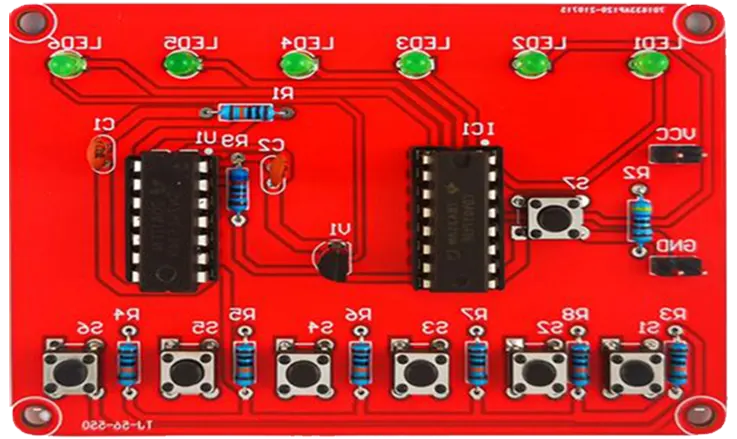
Outer Layer, Solder Mask and Finish
Outer layer processing repeats the imaging, plating and etching sequence, but on a surface that will later be assembled. After the copper pattern is complete, solder mask is printed and cured, leaving openings only at the pads and test points. The legend is then added, and a surface finish is applied to protect the exposed copper: hot air levelling, immersion silver, immersion tin, electroless nickel immersion gold or a hard gold layer for edge connectors.
The finish choice interacts with the assembly process and with the expected storage time. A finish that dissolves into the solder during reflow behaves differently from one that forms an intermetallic barrier, and the difference shows up in solder joint quality and in shelf life. After finishing, the outline is routed or punched and the board is ready for inspection.
Material Entry Standards
Process control starts before any copper is etched. Base laminate, copper foil, prepreg and solder mask ink are purchased against a specification that fixes the properties the design depends on, including dielectric constant tolerance and copper thickness tolerance. Incoming inspection verifies those properties on a sample basis, and material is stored under conditions that prevent moisture uptake, because a laminate that has absorbed water will release it during lamination and press cycles.
The reason for this discipline is that material variation cannot be corrected downstream. If the dielectric constant of a batch drifts, every impedance calculation made with the nominal value becomes slightly wrong, and no amount of process control during etching will recover the target. Controlling the input is cheaper than sorting the output.
Process Parameter Standards
During fabrication, a small set of parameters carries most of the quality risk. Trace width and spacing are held to roughly plus or minus ten percent of the design value, and controlled-impedance traces are held to about plus or minus ten percent of the target impedance, which is verified by measuring test coupons on the production panel rather than by assuming that a good etch produces a good impedance.
Hole metallization must reach a minimum copper thickness on the barrel wall, commonly 20 micrometres or more, and the distribution across the panel is monitored because plating is never perfectly uniform. The lamination profile is recorded and controlled for temperature ramp, pressure and vacuum, since a deviation there produces voids or delamination that may only appear after thermal cycling in the field.
Inspection and Acceptance Standards
Finished boards pass two levels of inspection. Visual acceptance follows IPC-A-600, which defines what counts as an acceptable, a conditionally acceptable or a rejectable anomaly in the copper, the mask and the finish. Performance requirements follow IPC-6012, which covers the electrical and physical characteristics of rigid boards, including the plating thickness, the dielectric withstand and the conductor integrity that the design assumed.
Every board then undergoes a complete open and short circuit test, with no sampling, because a single unconnected net will fail an entire assembly. Industrial control boards usually add tests that reflect their environment: thermal cycling to reveal marginal plating, insulation resistance measurement to confirm the dielectric, and sometimes a burn-in period. Keeping the test data with the panel record makes it possible to trace a field failure back to a specific production lot.
What the Fabricator Needs From the Designer
Fabrication standards only work if the design communicates what has to be controlled. A usable fabrication drawing states the stackup with material and thickness for every layer, the impedance targets and the layer each applies to, the minimum trace width and spacing, the hole sizes and the plating requirement, the surface finish, and the acceptance standard to be applied. It also specifies the coupon design so that impedance and plating can be measured on the panel.
Ambiguity is expensive on both sides. A board released with no impedance target forces the fabricator to ask, and every question costs a day. A stackup defined only by total thickness leaves the layer assignment open, so a supplier may choose a construction that meets the thickness but not the electrical intent. The general sequence is the same across suppliers, as described in PCB manufacturing processes, but the tolerances that apply to a specific build are worth confirming against PCB manufacturing tolerances before the file is frozen.
It also helps to state the operating environment. A board that will sit in an unheated outdoor cabinet needs different attention from one inside a climate-controlled rack, and the tests that verify quality should reflect the intended service life. The practices that keep yield predictable are collected in PCB yield and quality control, and the mechanical assumptions behind the panel, including how thickness is defined and measured, follow the PCB board thickness guide.
FAQ
How is hole wall copper thickness verified? By cross-sectioning plated holes on coupons taken from the production panel and measuring the copper on the barrel wall. Electrical testing alone will not reveal a thin but continuous barrel.
Why specify impedance tolerance separately from trace width tolerance? Because they are measured differently. Trace width is a dimensional check on the etched pattern, while impedance is an electrical measurement of a coupon and depends on the dielectric as well as the copper geometry.
Is a solder mask finish over pads ever acceptable? No. Solder mask is a dielectric and will prevent a reliable solder joint. Openings are defined by the mask artwork and should be checked against the pad layer before release.