Panelisation Design and Depaneling Method Choice for SMT
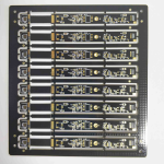
Panelisation is the practice of building several copies of a board in one panel so that the assembly line has something large enough to handle, and the way that panel is designed decides how the boards behave when they are finally separated. The choice between tabs and scoring, the width of the rails and the position of components near the edge are all made at the design stage and are expensive to change once the panel is released.
Why Panelisation Exists
A small board cannot be printed, placed and reflowed reliably on its own, because the machine transport, the stencil and the conveyor all need a minimum size and a stable edge. Grouping boards into a panel gives the line a workable format and lets one print stroke serve several products.
Panels also improve material utilisation, since the fabricator can nest boards to reduce waste from the laminate sheet. The panel is therefore a compromise between what the assembly line wants and what the material supplier can cut economically, and both sides should be represented in the decision.
Board Spacing and Rail Design
The spacing between adjacent boards has to be wide enough for the router bit or the scoring wheel and for the breakaway tab, and wide enough to allow the depaneling equipment to reach the cut. Routing typically needs more space than scoring, because the cutter has a diameter that has to fit between the boards.
The rails carry the panel through the line, so they must be wide enough for the conveyor and stiff enough not to sag in the oven. Rail width is also a cost decision, because every millimetre of rail is laminate that is not a product, and a panel with generous rails may cost more than the boards inside it.

Breakaway Tab Design
A tab holds two boards together until they are separated, so it has to be strong enough to survive printing, placement and reflow, and weak enough to break cleanly by hand or in a fixture. The width, the number of tabs and their position around the outline all contribute to that balance.
Tabs are usually placed where they can be broken without stressing a component, which means away from the corners of a heavy part and away from the edge of a fragile package. Our breakaway tab notes describe the geometry and the residual nub that is left behind.
V-Scoring and Its Limits
Scoring cuts a V shaped groove along both faces of the panel so that the board snaps along a straight line. It is fast, it costs almost nothing to add, and it produces a clean edge on a rectangular board with a generous rail.
It also has limits. Scoring only works on straight lines, it leaves a small amount of material that has to be broken, and the depth of the groove has to be controlled precisely because the remaining web determines whether the panel survives assembly. Our board outline notes cover the tolerance side.
Router Depaneling and Finish Quality
Routing cuts the outline with a small cutter that follows the profile, so it can produce curves, internal cutouts and a finished edge that looks like a machined part. It leaves a smoother edge than scoring and generates far less stress at the cut.
The cost is time and tooling. A router programme has to be written and verified, the cutter wears and has to be changed, and the process generates dust that has to be extracted. For a board with a complex outline or a component close to the edge, the quality is usually worth it.
Fiducials, Tooling and Machine Access
The panel needs its own fiducials, placed so that every board position can be located from a common set of marks. Where the placement machine indexes by board rather than by panel, local fiducials beside each board are what keep the placement accurate across the whole panel.
Tooling holes locate the panel in the printer, the placement machine and the depaneling fixture. They should be placed in the rail rather than in the product, and they must be present on the first and last board position, otherwise the panel cannot be referenced reliably at the ends.
Component Keep-Out Near the Edge
Components should be kept away from the break line by a distance that reflects the depaneling method. Hand breaking a tab flexes the board and can crack a capacitor a few millimetres away, while routing and scoring apply forces in a more controlled way.
The keep out also has to allow for the conveyor and for the clamps that hold the panel. A tall component at the leading edge will collide with the machine, and a part hanging over the rail will be damaged by the stencil printer during the print stroke.
Cost, Yield and Handling Trade-Offs
A larger panel spreads the fixed cost of the tooling over more boards, but it also concentrates risk. If a defect appears at one position, the whole panel may have to be scrapped, and a warp in a large panel can ruin every board on it at once.
Very small panels are easier to handle but increase the number of transport cycles and the amount of setup time. The economic panel size is usually found by looking at the assembly line constraints first and the material cost second, rather than the other way round.
Approving a Panel Before the Run
The panel layout should be approved by the assembly team before the artwork is released, because the constraint that matters most is usually a machine limit that the designer never sees. A drawing review with the line engineer costs an hour and prevents a scrapped production panel.
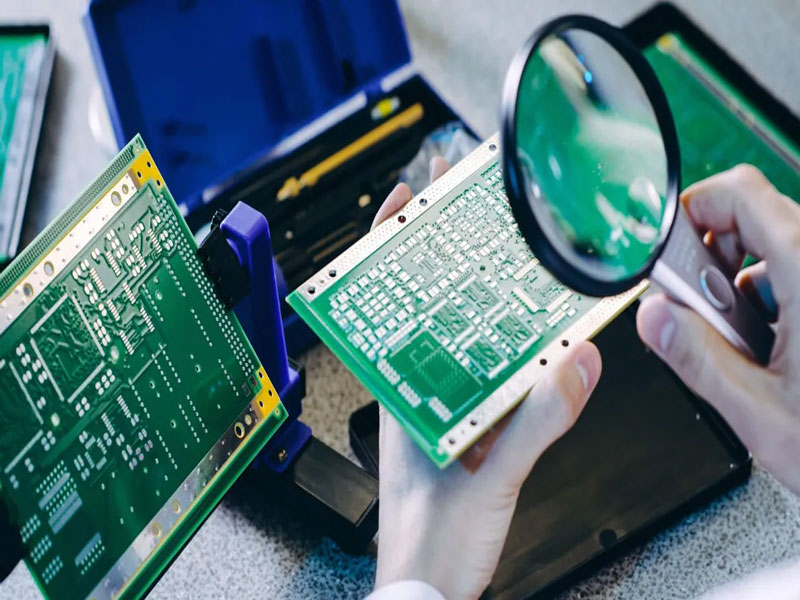
The final check is a trial depaneling run on a bare or scrap panel, which shows whether the tabs break as intended and whether the edge meets the customer requirement. Our design release and fabrication notes checklists list the points worth confirming.
Process Control and Verification
On a design of this kind, depaneling is the item that decides how the rest of the board is arranged. The measurements that matter are the repeatable ones: conductor width and spacing, annular ring, finished hole size, plating thickness and surface finish are all verifiable on a coupon that travels with the panel. Running a first article through the same checks as the production panel confirms that the two agree, and that comparison is the cheapest form of process control available at prototype stage.
FAQ
Should tabs or scoring be used? Scoring is faster and cheaper on a rectangular board with a straight edge. Tabs or routing are needed where the outline is curved, where components sit close to the edge, or where the residual stress of breaking would damage a part.
How wide should a breakaway tab be? Wide enough to survive assembly and narrow enough to break without a tool. The value depends on the material, the board thickness and the support around the tab, so it is usually set by experiment on a trial panel.
How does gopcb help with panel design? We review the panel against the material sheet and the assembly constraints, confirm the rail and tooling layout, set the tab or score geometry with the customer, and supply a trial panel so the break can be tested before the run.