Schematic Design Steps Before PCB Layout Begins
The schematic is where most layout problems are created, because a decision that is cheap on a drawing can be expensive on a board. Reference designators, net naming, test access and the split between supply domains all originate here. This guide describes the schematic design steps that make the layout straightforward rather than a negotiation.
Why the Schematic Decides the Layout
It also decides how much the board will cost. A schematic that spreads a function across four corners of a sheet pushes the layout to spread the components, and area is what the fabricator prices. Grouping components by function in the drawing makes a compact layout the natural outcome rather than a struggle.
A layout can only arrange what the schematic defines. If the schematic mixes analogue and digital returns, the layout has to invent a boundary. If it leaves test points unspecified, they have to be added late. If it treats a supply as a single net with no structure, the layout has to guess where the current flows.
Those are not layout problems; they are schematic decisions that were deferred. Making them at drawing stage costs nothing and removes a class of rework that would otherwise appear after the first board is built.
Step One: Define the Blocks
Each block should state its supply and its current. A block with no stated current cannot be checked against the regulator that feeds it, and that check is exactly the one that is missed when a design draws too little current on paper and too much in practice.
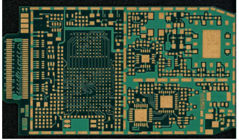
Start by dividing the circuit into functional blocks: power input, conversion, analogue, digital, radio, interface and so on. Each block should have a clear boundary, a supply and a return path. Blocks that share a return should be identified, because that sharing is the origin of most noise problems.
The boundary is also where isolation is defined. Where two blocks must remain galvanically separate, that separation has to be visible in the drawing, not inferred by the layout engineer from the components involved.
<img src="https://www.gopcba.com/wp-content/uploads/2026/08/pl149813980-oem_fast_turn_custom_pcb_rigid_enig_printed_circuit_board_quick_turn-1.webp" alt="Schematic design steps showing block definition and netlist handover” />
Step Two: Build and Audit the Component Library
Every symbol should correspond to a verified footprint, and the pair should be audited before it is used. A symbol with the wrong pin numbering produces a netlist that is wrong in a way no rule check can detect, and the error travels all the way to the assembled board.
The audit is a physical check: print the land pattern at one-to-one scale and place the component on the drawing. It catches a surprising number of library errors, and it is the single most effective protection against an unusable first board.
Step Three: Draw for Readability
Net labels should be used instead of long routed lines. A drawing crossed by dozens of long connections is difficult to review, while one that uses labelled stubs grouped by function can be read block by block. The netlist is identical; the review quality is not.
A schematic is read far more often than it is drawn. Signals should flow left to right, power rails should run at the top and returns at the bottom, and components should be grouped by function rather than by reference number. A reviewer who can follow the drawing finds more errors.
Connector pin assignments deserve particular care. A connector drawn with pins in their physical order is easier to check against the mechanical drawing than one drawn logically, and the mechanical interface is where most integration mistakes originate.

Step Four: Assign Nets and Test Points
Pull-up and pull-down resistors deserve an explicit listing. A pin that floats during power-up behaves unpredictably, and the remedy is usually a resistor that was omitted rather than a component that was wrong. A checklist of every pin that must not float is a cheap safeguard.
Net naming is a design decision. A name that states the function, the voltage and the domain is self-documenting, while an auto-generated name states nothing. On a mixed-signal board the naming is what shows the layout engineer which nets belong together.
Test points should be assigned at the same time. Every net that will need to be measured during bring-up should have one, and the expected probe type should be recorded. Applying manufacturable design guidelines to the test point geometry keeps them usable rather than decorative.
Step Five: Run the Rule Check
Voltage ratings belong in the same pass. A capacitor rated below the rail it sits on is a reliability problem, and cross-checking the rating against the net voltage is a mechanical exercise that a script performs far more reliably than a reviewer.
A design rule check on the schematic catches unconnected inputs, conflicting outputs, single-pin nets and missing power flags. It does not catch a wrong pinout or a wrong component value, but it removes the mechanical errors that would otherwise occupy the review.
Running the check before the review rather than during it is what makes the review productive. A meeting spent on unconnected pins is a meeting that does not examine the mixed-signal partitioning or the return paths, which are the decisions that actually matter.
Step Six: Review and Release
The review record should be kept with the release. When a question reappears at the second revision, the earlier answer is available without reconstructing it, and the accepted risks stay visible instead of being rediscovered by the next person to open the file.
The design review should ask questions with checkable answers: is every supply decoupled at the pin, is every interface accounted for, is the reset behaviour defined, and can every critical net be probed. Each answer closes an item or records an accepted risk against a name.
Release means freezing the netlist and issuing a revision number. From that point the layout works against a fixed reference, and any change becomes a visible revision rather than an informal adjustment that nobody can trace later.
Handing Over to Layout
The handover should also note what is still open. Known uncertainties, such as a value that will be tuned on the bench, are useful information for the layout engineer, who can then reserve space rather than route into it and have to move it later.
The handover should include more than a netlist. A block diagram, the stackup intent, the critical nets and any mechanical constraint make the layout faster and more accurate, and they prevent the layout engineer from re-deriving decisions that were already made.
It also helps to say what the board must not do. Constraints that are stated as prohibitions, such as keeping a switching node away from a sensor, are more useful than general guidance, because they identify the PCB construction decisions that matter most for this particular design.
FAQ
How much detail should the schematic carry? Enough that the layout can be completed without asking questions. Block boundaries, supply domains, test points and critical nets all belong in the drawing rather than in a conversation.
Should connectors be drawn logically or physically? Physically, wherever the pin order matters mechanically. Drawing the connector as it appears on the mating part makes the integration check a visual comparison rather than a cross-reference exercise.
What does a rule check not catch? Wrong pinouts, wrong values and wrong footprints. Those require a library audit and a review against the datasheets, which is why the audit is worth doing before the layout begins.