Thermally Separated Metal Core PCBs for Power Electronics
An aluminium backed board is an efficient way to remove heat from a power component, but it has a weakness. The dielectric layer that insulates the circuit from the metal base is thin and is a much poorer conductor than the aluminium, so the heat path is dominated by that layer. Where a circuit has both high current conductors and small signal traces, the area available for the thermal path competes with the area needed for routing.
The thermally separated construction resolves that competition by giving the heat generating pads their own path to the metal base, isolated from the general circuit area. In effect the board is divided into a thermal region and an electrical region, and the design work lies in deciding where the boundary falls and how the two regions are connected.
What Thermal Separation Means
In a conventional metal core board the copper pattern sits on a continuous dielectric layer bonded to the aluminium base, and heat flows from any copper area through that layer into the base. The dielectric is typically 75 to 150 micrometres thick and conducts heat at one to three watts per metre kelvin, which makes it the largest thermal resistance in the stack.
A thermally separated construction reduces that resistance where it matters by removing the dielectric from selected areas, so that the copper is connected to the aluminium base directly through a metal to metal path, or by thinning the dielectric locally. The rest of the board keeps the standard dielectric, which preserves the insulation and the breakdown voltage for the signal and control circuitry. The result is a board with a low thermal resistance under the power devices and normal isolation everywhere else.
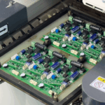
<img src="https://www.gopcba.com/wp-content/uploads/2020/12/ptt_getintouch.jpg" alt="Metal core PCB with a direct thermal path under a power device” />
Where It Is Used
The obvious application is a power stage that has to be compact: a motor drive, a dc to dc converter with a small footprint, or an LED module with a high luminous flux. In each case the device junction temperature is the limiting factor on the rated output, and reducing the thermal resistance of the substrate allows either a higher power or a smaller heatsink for the same power.
It is also used where the board is the structural element of the product. When the aluminium base carries the mounting features and the device is bolted to it, the dielectric layer is not only a thermal resistance but also a mechanical interface that has to survive the mounting force. A direct metal path avoids the risk of the dielectric cracking under a fastener and removes the need for an insulating pad with its own thermal resistance.
Construction and Process
The direct path is made by forming a cavity or a stud in the dielectric before it is bonded, or by bonding the copper to a raised feature on the aluminium base. The bonding process has to produce a reliable joint without damaging the dielectric around it, and the resulting surface has to be flat enough for the component to be soldered or sintered. Where the path is made by a metal stud through a hole in the dielectric, the stud also carries the mechanical load.
Registration between the cavity and the copper pattern is critical because the copper has to cover the exposed metal area with a defined margin. The layout therefore needs to account for the tolerance of the cavity position, which is normally larger than the tolerance of the copper pattern itself. Aligning the thermal pad of the device to the cavity, and keeping the copper pad larger than the cavity by at least the positional tolerance, is the standard approach.

Electrical Isolation Must Be Maintained
The point of the dielectric is to isolate the circuit from the metal base, which is usually connected to the chassis or to a heatsink at earth potential. A direct thermal path removes that isolation in the area where it is created, so the copper pad that connects to the base is at the potential of the base. This is acceptable when the device tab is intended to be grounded, as it is in many power packages, and unacceptable when the tab is a live node.
The design must therefore establish which nodes may be connected to the base and which may not. Where isolation is required, the base itself can be isolated from the chassis with a separate insulator, or the device can be mounted with its tab isolated and the thermal path routed through a local thinning of the dielectric rather than a direct connection. Getting that decision wrong produces a board that either fails the insulation test or does not deliver the thermal performance it was designed for.
Thermal Simulation and Measurement
A thermally separated board is worth simulating before it is built, because the difference between a direct path and a standard dielectric is large and easy to model. A simple finite element or thermal network model of the device, the solder joint, the copper pad, the dielectric and the base gives a junction temperature estimate that is accurate enough to size the heatsink. The model should include the spreading in the base, since the aluminium conducts heat laterally much better than the dielectric and the base is part of the path.
Measurement after assembly confirms the model. A thermocouple on the base and a measurement of the device case temperature give the thermal resistance of the joint and the substrate, and comparing that with the calculation shows whether the cavity was bonded properly. Where a batch shows a higher resistance than expected, the bonding of the thermal path is the first item to examine. Producing a coupon with the same thermal features as the product, and measuring it before production, is the cheapest way to keep the thermal management of the design under control.
Design Checklist
Before releasing a thermally separated board, the following items are worth confirming. The nodes that may be connected to the base are identified, and the ones that may not are insulated. The copper pad covering each thermal cavity is larger than the cavity by at least the positional tolerance of the cavity. The dielectric elsewhere is thick enough for the required breakdown voltage, including the edges of the metal base. The solder joint or sinter layer over the thermal path has a defined thickness and a defined void criterion, since a void in that joint defeats the purpose of the design. Finally, the mechanical mounting does not apply a bending load across a cavity, because the reduced dielectric area is also the weakest part of the board.
Each of these items is a consequence of the same decision, which is that the thermal path and the electrical isolation have been separated deliberately rather than left to the properties of a single dielectric layer. Documenting that decision, and the assumptions behind it, makes the board easier to modify and much easier to manufacture consistently.
Additional Considerations for This Build
Related reading: our fabrication notes, board quality and design release notes cover the same ground.
FAQ
Is a thermally separated board the same as a metal core board with a thick dielectric? No. The separation reduces the thermal resistance rather than increasing it, by removing or thinning the dielectric in selected areas while keeping it elsewhere.
Can a live node be thermally connected to the base? Only if the base itself is isolated from the chassis. Otherwise the thermal path has to be made through a dielectric that is thin enough to conduct but thick enough to isolate.
What limits the power that can be handled? The junction temperature of the device and the thermal resistance from the junction to the ambient. The substrate is one term; the solder joint and the heatsink are often equally significant.