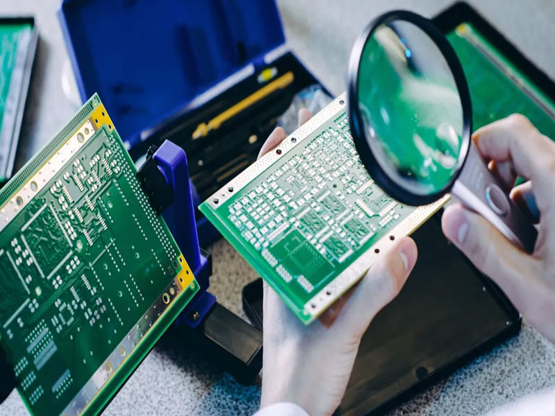
Assembling MEMS Microphone Packages on a PCB
A micro electro mechanical microphone contains a moving membrane a few hundred nanometres thick, a back plate with acoustic holes, and an application specific integrated circuit that buffers and digitises the signal. The three are packaged together in a cavity with a sound port, and the package is then placed and reflowed like any other surface mount component.
What makes the part interesting from a manufacturing point of view is the interaction between the acoustic design and the assembly process. The port has to be open, the cavity volume has to match the design, and the seal between the package and the board has to be airtight, because a leak changes the low frequency response and lets flux and cleaning chemistry into the cavity.
Inside the Package
The membrane and the back plate form a capacitor whose capacitance changes with sound pressure. A bias voltage is applied, and the small capacitance change is converted to a voltage by the ASIC. Because the signal is at the level of a few millivolts at conversational sound pressure, the amplifier has to be close to the transducer, which is why the ASIC sits in the same package rather than on the board.
The package is a small land grid array with a sound port on the top or on the bottom. The internal cavity volume and the acoustic resistance of the port together form a low frequency roll off, and the design is tuned for a specific response. Anything that changes the cavity volume or the port impedance shifts that roll off, so the mechanical interface to the board is part of the acoustic design.
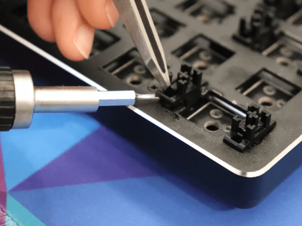
Top Port and Bottom Port Assemblies
A top port microphone takes sound through the lid, so the port on the board can be closed and the board acts as a mechanical support only. A bottom port microphone takes sound through the board, which means the board needs a hole aligned with the port and the seal between the package and the board has to be airtight around it. The bottom port arrangement gives better protection because the package lid faces away from the sound opening, and it is common in handsets.
The board hole is a feature with its own tolerance. It has to be large enough not to obstruct the sound, small enough not to weaken the seal, and positioned within the tolerance that the seal can absorb. A gasket or a ring of solder mask around the hole is often used to define the sealing surface, and the paste aperture around the package has to be designed so that the solder does not flow into the hole. Where the hole is drilled or routed, burrs inside the hole can obstruct the port, so the board process should specify how the hole edge is finished.
Sealing and the Reflow Process
The seal between the package and the board is made by the solder joints around the perimeter of the land grid array. The joints have to be continuous, which requires a well controlled paste volume and a reflow profile that produces a void free fillet. A gap in the seal lets air leak between the front and the back of the membrane, which reduces the low frequency output and lets contamination in.
Reflow also affects the internal adhesive that bonds the lid. The package is rated for a lead free profile, but the time above liquidus has to be within the supplier specification, because the adhesive continues to cure and can release volatiles that condense on the membrane. The atmosphere matters as well: a nitrogen atmosphere reduces oxidation, and it also reduces the amount of flux residue that can deposit inside the port.

Cleaning and Contamination
Cleaning a board that carries a bottom port microphone is a compromise. Water based cleaning can force liquid through the port if the pressure is high or if the seal is imperfect, and residue that dries inside the cavity changes the membrane mass and therefore the response. The usual approach is a no clean process with a low residue paste, or a cleaning process that has been qualified on the specific package and verified by acoustic measurement afterwards.
Contamination shows up in the acoustic measurements rather than in a visual inspection. A membrane with a deposit on it has a different resonance, which appears as a change in the high frequency response, and a partially blocked port reduces the low frequency output. Measuring the response of a sample from each build, and comparing it with the reference, detects contamination before it becomes a field failure. That is the reason acoustic testing is part of the production test for any product that contains a microphone array.
Acoustic Testing in Production
The test is normally performed in a small chamber with a loudspeaker that produces a defined stimulus, and the microphone output is captured and compared with a reference response and a sensitivity limit. The chamber has to be quiet enough and repeatable, and the coupling between the loudspeaker and the microphone has to be consistent, because the sensitivity measurement depends on both.
For a product with several microphones, the test also verifies the matching between them, which is what the beamforming algorithm relies on. Sensitivity differences of a fraction of a decibel matter in an array, so the test limits are tighter than for a single microphone. Recording the sensitivity of each unit, and tracking it over a production run, reveals a drift in the assembly process before it exceeds the limit. Handling the acoustic interface with the care it deserves is part of the same discipline as any other mixed signal design, where a small physical change produces a large functional one.
Design and Assembly Checklist
The items worth confirming before release are the port alignment between the package and the board hole, the sealing surface and its flatness, the paste volume and aperture design around the land pattern, the profile against the supplier limit, the cleaning decision and the acoustic test limits with their tolerances. Each of these is a small detail, and each of them has been the cause of a production problem at some point.
The list is also the basis for the documentation package. A drawing that shows the port, the gasket and the sealing surface, together with the profile used and the acoustic limits, allows the assembly to be reproduced and a problem to be diagnosed without disassembling a good unit for reference. That is what makes a microphone assembly controllable rather than dependent on the experience of the people running the line.
Placement Accuracy and Nozzle Choice
The microphone is placed with a vacuum nozzle, and the nozzle has to contact a flat area of the lid rather than the port. On a top port part the port is on the lid, so the nozzle has to be smaller than the port or offset from it, and the placement force has to be low enough not to deform the lid. A nozzle that covers the port can also pressurise the cavity and momentarily deflect the membrane, which is harmless in itself but is a sign that the handling is rougher than the part expects.
Placement accuracy matters for a bottom port part because the package has to sit over the board hole with the seal continuous all around. The positional tolerance of the placement and of the hole both contribute, and the sealing surface has to be wide enough to absorb the sum of them. Where several microphones are used, their relative positions also determine the performance of the array, so the placement accuracy of each device becomes part of the acoustic specification as well as a mechanical one.
Additional Considerations for This Build
Practical attention to acoustic seal pays for itself here, because it decides whether the finished board behaves as the drawing intended. Where the requirement is not stated on the fabrication drawing or in the assembly notes, the shop has to assume a default, and that default is rarely the value the design was simulated with. Stating acoustic seal explicitly, together with the tolerance that applies, removes the assumption and keeps the result predictable from batch to batch.
Deliberate attention to sensitivity test pays for itself here, because it decides whether the finished board behaves as the drawing intended. Where the requirement is not stated on the fabrication drawing or in the assembly notes, the shop has to assume a default, and that default is rarely the value the design was simulated with. Stating sensitivity test explicitly, together with the tolerance that applies, removes the assumption and keeps the result predictable from batch to batch.
Related reading: our fabrication notes, board quality and design release notes cover the same ground.
FAQ
Can a bottom port microphone be cleaned with water? Only with a qualified process. Pressure and dwell time have to be controlled, and the acoustic response should be verified after cleaning.
Why does a seal leak matter? It lets air move between the front and the back of the membrane, which reduces the low frequency output, and it allows flux and moisture into the cavity.
Do all microphones in an array need the same sensitivity? They need to be close, because the array algorithm depends on their relative response. The limits are tighter than for a single microphone.